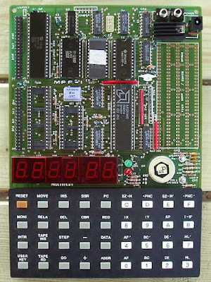
This time, it's said. I close the topic 'µPF--1 clone'
Why? Because it works.
A few years ago, when I set out to attempt to replicate Wichit Sirichote's work in FPGAs, I developed a minimal system based on the sources of Wichit Sirichote. It had already taken me quite a bit of time to translate all the hardware onto a commercial FPGA board, then develop a personal board to accommodate an FPGA module. I found that it would have taken me too long to re-write a complete system based on poor quality of the source provided.
And then, I wanted to test the GoWin FPGAs. When I say testing, I mean creating an FPGA board and then programming a complete system. That is to say also test the GoWin development tools.
 |
Free advertising ;-)
|
After seeing that the small computer created 'seems' to work fine. I decided to attack what is the center of interest of such a small computer, namely the operation in step by step.
Until then, I had contented myself with re-writing the source of Wichit Sirichote to allow the manipulation of addresses and data as well as the loading of programs by serial link. So I missed the step by step. In terms of real learning of processor operation, step by step is extremely interesting!
It's quite interesting to be able to modify a program value almost on the fly, then to check the result by immediately restarting the program. That's the whole point of such a computer.
It's a personal opinion, but I find it much more relevant than working on Arduino modules as a discovery of computing.
The system set up for step by step operation is based on an interrupt triggered after a certain number of pulses of the signal M1. Interesting and very functional system. On this point, Wichit Sirichote's source served me well.
So there you go, I have everything set up except the 'REL' key. I couldn't figure out its usefulness, even studying the provided source well. Regardless, it is now possible to write an entire program by directly entering the processor codes, or more simply by loading the program via the serial link and modifying the code directly on the keyboard, starting then stopping the program to check the content of processor registers etc etc...
Small example of a program loaded via the serial link:
The system is therefore validated. The GoWin FPGA used works perfectly. It is a success. I forgot, the serial link works perfectly, here at 115200 Bauds, and not faulty at 1200 Bauds as on Wichit Sirichote's system ;-)
In terms of FPGA resource usage, this is what it looks like:
Barely more than half of the resources in logic gates. I haven't implemented expansion port management, but it only takes a few dozen logical units. Not bad at all!
What's next?
I will now try to set up an HDMI output based on these Gowin FPGAs. Because I would like to develop a real computer with screen and keyboard on which it would be possible to choose the type of processor wanted.
This kind of machine has already been built, notably by Jeri Ellsworth in 2002. It's been just 20 years. It did not meet with much success while the retro-computing craze started to really emerge from the 2010s.
This machine may have come out too soon...
Stefany Allaire is currently recreating a whole range of computers on the same principle. You can visit his website c256foenix.com particularly with regard to its new C256 FOENIX JUNIOR, based on a 6.29MHz WDC W65C02S processor :
 |
| Free advertising ;-) |
I am really impressed with the quality of his work...
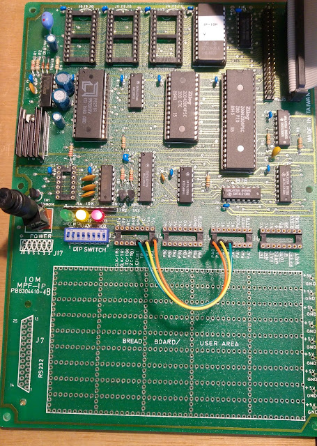
[ 07-16-2022) Small update : And now the test with the IOM MPF-1P expansion board.
In fact, I knew that testing the connection of my processor board on the IOM board was going to pose a potential problem. simply because a number of signals used to manage the expansion port are also used for the JTAG programming interface.
In fact it is not that complicated. All that is needed is to dynamically control the FPGA programming management system. Once done, the operation of the external bus is instantaneous. The connection of the IOM is therefore completely normal. I completed my little test program to turn on the diodes on the IOM board. It works without any problem!
GREAT :-)
The 'funniest' part of the story is that while I added some logical ressources to manage the expansion port, the GoWin software summary report tells me a 50% logical resources usage . It was 52% previously:
I could put two systems like this in the used FPGA considering only the logic resources. However, I wouldn't have enough internal memory for that...
[ 07-18-2022) Small update : For fun, I also connected the small printer, here the PRT-1P model to my processor board :
It seems to work. Why do I say 'seems'? Because I don't own thermal paper. So I can not check if the message is printed correctly. All I can say is that the printer responds correctly to requests made through routines present in the ROM integrated onto the printer board.
I have no idea where to get thermal paper for this machine. Occasionally, I'll try to find some...


