Since the September term started, I haven't been idle.
The first topic I tackled is the flash cartridge for MSX computers.
To recap, it's been almost two years now that I've been trying to develop a cartridge for MSX computers, originally intended to include only FLASH memory that could be programmed directly via file transfer from a PC/Mac/Linux.
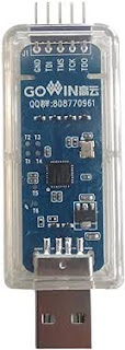
I first developed this cartridge using a fast processor of Chinese origin and of the RISC-V type. Then, two processors, because at the time I was using the concept of copy/pasting to the cartridge, which was seen as a small USB key, the constant interruptions from the PC's USB port ended up causing the MSX computer to behave erratically. I also evolved the concept to allow for a hardware RESET of the MSX computer during the loading phase.
However, although this cartridge worked very well on the MSX machine I owned, a clone created by Sergey Kiselev, the cartridge worked randomly on other machines.
It's true that I was using the speed of the embedded processors to present the Flash content directly to the MSX during read operations from the Z80.
 |
| The Sergey Kiselev MSX system. https://github.com/skiselev |
And therefore, the timing of the MSX bus signals must be precise.
Having observed these issues, I decided to use a processor from the STM32 family this time, which is twice as fast. I also changed the loading concept. I now use the YMODEM protocol via a serial link, instead of a disk-to-disk file transfer. Furthermore, this allows me to control the file reception process very precisely, including verifying its integrity.
The new cartridge was very pleasing visually because it was much simpler than the previous versions. But... I never managed to get an MSX program to start from its contents. I then realized that I didn't have precise specifications for the maximum operating speed of the GPIO pins on the STM32 processor I used. The configuration software only offers three speed levels named Low/Medium/High: not very precise!
I should have used a logic analyzer to see what was really happening, but after running a few tests, I realized that the processor was capable of changing its output GPIOs very quickly. However, the problem lies in its reaction time relative to its inputs.
Conclusion: perhaps an RP2040 or a more recent processor could have done the job, but I never had the opportunity to evaluate that type of processor, so I moved on to a new hardware concept: the FPGA.
The idea is to connect the flash memory directly through wired logic, rather than providing the data from a processor executing code.
The problem is that FPGAs are relatively expensive compared to RISC-V or ARM microcontrollers. This is also true for CPLDs, which are simpler and could still have been suitable, but to which I would have had to add a file reception and processing processor anyway.
So the resulting idea is simple: implement in an FPGA the logic for multiplexing access to the FLASH memory, allowing accessibility on one hand by the MSX computer, and on the other hand by the cartridge's embedded processor to program the file received from the PC. Also, to implement within it the processor for receiving and processing data from the PC.
Among the range of FPGAs available on the market, one brand offers FPGAs at a very competitive price: Efinix. It should be noted that there is a reason why these FPGAs are more affordable. They don't offer exactly all the features that a more standard FPGA might have. Having worked a bit with these circuits, I know what their limitations are, and I am therefore in a position to know that this does not pose a problem for my project.
 |
| An affordable dev board. |
So, I ran a few tests with a small Efinix development board. I implemented the RISC-V processor provided as an IP core by Efinix. This processor works very well, and, as an added bonus, its programming and debugging are done in real-time using a specific version of Eclipse.
The only difficulty I encountered was getting the Eclipse environment to recognize the JTAG probe I bought on Aliexpress. The problem was with the JTAG probe itself. I had to perform a small programming operation on it to get it to work correctly.
 |
| FTDI Chip USB to MPSSE Cables |
I'm not criticizing the AliExpress vendor for their prankster side, but in terms of fair play, there's room for improvement!Once these tests were completed, I decided to have a small extension board made, providing FLASH and SRAM, because I figured that it would make the cartridge more versatile. It also includes the USB port for communication with the PC, as well as the necessary connectors for programming and real-time debugging of the processor.
The phase of managing the YMODEM protocol should be fairly easy to implement, given that I have already coded this part for the previous version of the cartridge based on the STM32 processor.
For now, I've only compiled the processor's 'blink' test. I still need to at least understand how it works, especially its interrupt handling. But I should be able to manage it.
 |
| The development board and its expansion board. |
And now, for VGA. What?
Why spend time on a VGA interface?
Well, actually, I've been looking into this for several years. Originally, I never learned VHDL or how to use FPGAs in an academic setting. The way I discovered this environment was probably not the right one. But over the years, I ended up developing my own personal perspective on the subject. Furthermore, I've wanted to create this type of interface for quite some time—a persistent desire to pursue the idea of the Atari STE, without any pretense, of course.
Looking back, I must say that the VHDL/FPGA duo isn't really difficult for anyone who has even a basic grasp of combinatorial and sequential logic. After all, VHDL is just a high-level language suited for representing logical structures.
No, what presented a real challenge for me was that to create your first example, the famous 'blink', you need to have a minimum grasp of a certain number of technical concepts and realities. In fact, the barrier to entry is a bit high for a beginner. This is especially true if you want to embark on the System-on-Chip (SoC) adventure.
Regarding the management of a VGA framebuffer, the problem for me was the type of memory implemented on the FPGA board I had bought at the time: a DE2-70 :
This board is absolutely brilliant and has, I should say had, everything needed to start a somewhat 'complex' development. Yes, because there's no HDMI video output, for example, only VGA.
Except... there is no simple SRAM memory available. There is SRAM, yes, but it's synchronous. So what? Wouldn't that work for VGA? Well, yes, obviously; in fact, it might even be perfectly suited for it. Those familiar with 'burst' operations will know what I'm alluding to. Nevertheless, for a beginner, it doesn't allow for easy debugging, for instance. Could my SRAM access 'functions' be causing issues? Or perhaps my VGA processing core? As you can gather, it multiplies the potential sources of problems, and when you're not comfortable with the concept, it can lead to a lot of frustration. That was my case.
So, a word of advice: to get started with FPGAs, first choose a simple board with LEDs, switches, SRAM, and extensions like an LCD display and HDMI output. You can always acquire a more advanced board later if you wish, but to start with simple projects, use a simple board
Although I managed, a few years ago, to create 'something' that allowed me to display pixels on the screen, I clearly understood that there was something 'stuck' in my concept. Over time, I had even envisioned another way of doing it.
And it is precisely the fruit of my reflections that I have decided to test. Undoubtedly because I felt the time had come to put my ideas into practice.
There's nothing revolutionary in what I'm doing. People working on this kind of subject have undoubtedly encountered the same problems as I have. But well, to be able to envision something, you need to know that you'll know how to do it...
So, I created a small extension board with two SRAM chips for the FPGA DE2-70 board. And I started coding.
It took me just over a day to already succeed in reading the contents of the SRAM. Random content, since it's not erased when the FPGA board is powered on.
I then tackled the system's input, meaning I arbitrarily and sequentially imposed a color pattern:
At this stage, I must say I was starting to think I was potentially on the right track this time to create my VGA framebuffer. This image indicated to me that I had managed to handle the various system asynchronous timings reasonably correctly.
To confirm the validity of my solution, I still needed to fill this framebuffer from an external source, as a microprocessor would do. To achieve this, I used a development board with an STM32 processor. Admittedly, while this type of processor can be a bit slow to react to changes in the state of its input GPIOs, it is capable of changing the state of its outputs at high speed.
To do this, I connected a GPIO port of the FPGA to an extension connector on my add-on board. After establishing a minimal communication protocol between the processor board and the framebuffer input, I connected this processor board to my add-on board.
I had to make slight adjustments to some timing issues, such as the length of certain memory zones, to achieve a satisfactory result:
This result is achieved by injecting pixel codes directly into the framebuffer from the STM32 board. The visible shift in the image occurs because I pushed the STM32 processor to its limit to prevent on-screen interference. The photo was taken while the image was constantly moving, hence this shift.
In reality, I can completely fill this 640*480 screen between 3 and 4 times per second, despite using an 8-bit interface where each pixel can display 256 colors (requiring one byte per pixel). Furthermore, because I'm using the free version of Quartus, I cannot use different frequencies for my VGA engine core and the display frequency.
Given that the display frequency is about 25 MHz and the memories are rated for 100 MHz access, I could potentially accept input into the framebuffer at 3 to 4 times the current rate. And if the processor had a 32-bit bus instead of 8-bit, I could multiply the speed by another factor of 4. This could potentially give me a refresh rate of about 50 Hz to 60 Hz per second. Not bad for a relatively simple system.
Of course, I still have to implement a graphics processor, to handle internal operations—and thus faster—such as moving blocks, sprites, etc.... That will be the next stage of my development.
It's possible that all of this could be done with an RP2040 or 2050, I'm not sure. I've seen several examples to that on the web. And in fact, I'm currently trying to set up the development toolchain for Raspberry in Visual Studio Code. The Raspberry add-ons not being up to date, for now I can compile 'blink' for the RP2050 and load the executable by copying and pasting into the RP2050's disk space.
However, I can't get the debugger to work. I realized that the installed version of OpenOCD is largely outdated and is missing the description file for the RP2050. I hope that loading the latest version of OpenOCD will solve my problem. Really, for an automatic installation, there's room for improvement.
And so, my Drumulator project? On standby for the moment, I must admit...


