vendredi 1 juillet 2022

Chinese components and GoWin FPGAs. Is it worth?

It's been a few years since I mentioned the rise of China in the supply of original components. GoWin is one of those companies that for several years has developed a series of FPGAs.


So I thought it was time to try this type of components. For this I managed to get the programming tool GWU2X :


The development software tool is available directly on the GoWin site. I also had to find a development board equipped with an original GoWin FPGA. I couldn't really find what suited me on the market, so I decided to develop my own board, in Qmtech format, since I had developed a few projects with this board format: 


Very recently, I managed to implement the 'Hello World' (the blinking led) on this board. The next step was very ambitious, namely trying to implement a complete Z80 system within this FPGA. 

So, I chose to try installing the Microprofessor version 1B system on the electronic board dedicated to this small vintage computer:

The uPF--1 original board
It took me a few hours to familiarize myself with the GoWin development environment, as well as to make the necessary small modifications to my VHDL code to make this FPGA compatible with the uPF--1 system. 

So, after a few hours of work, the result is there:


I did not attempt to implement all the hardware resources of the uPF--1, that was not the goal. I just wanted to see if I could get the same services with this FPGA as with the ones I usually use like Altera (Intel now) circuits. The goal is reached. I now think I can continue to develop using these GoWin circuits.

Conclusion: I appreciate these circuits which seem to me easier to use than the Xilinx or Altera circuits. The entire development chain is easy to understand. The necessary resources are available on the web. There are few ways of doing of the software development that could be improved a bit. But this is more of a personal matter...

In short: practical component to use. Easy to use development chain: cool!

lundi 20 juin 2022

GOWIN FPGA

I'm always looking for easy to use components. As far as FPGAs are concerned, their implementation is not always easy nor always cheap (multi-voltage, external EEPROM, etc.)

As a result, I had noticed that the series of FPGAs from the GoWin brand, seemed relatively simpler to implement than the major standards such as Altera or Xilinx.

So I decided to make a prototype board. I chose the module format offered by QMTECH because I have some developments that use them. This way, I can eventually place the GoWin module instead of the QMTECH modules.

The result looks like this:


To be able to program these FPGAs, it is absolutely necessary to obtain the programming dongle. I chose the 'GoWin USB cable' (GWU2X). It's inexpensive and easy to install. The procedure of installation is described in the dongle documentation.

Once these elements have been purchased and made, all that remains is to connect them. The detection of the FPGA is done without problem. 

I had obviously made a mistake by setting up a resistance of bad value, subsequently replaced by one of good value (red circles).


If I publish this little post, it is obviously because the functional test has passed. The 'Hello World' works without problems. The user LED is flashing correctly.

I just got an example from GoWin and modified the output pins according to the characteristics of my module. 

Most of the work is done, ie the discovery and implementation of the entire development and programming chain. It now remains to really take control of this FPGA. This is a 4 000 gates model. I'll see if I can implement a minimum Z80 system there...

For this, I will use my µPF2 compatible board in which was currently inserted a QMETCH module equipped with Altera FPGA:

My GoWin FPGA-based module fits perfectly in place of the Qmtech module:

For the moment I absolutely do not know if I will be able to place a minimum system in this GoWin FPGA. I know that the number of gates used in the original design is less than 4000 gates so it should be fine but on the one hand I have no experience on the GoWin development tool, and I don't know if I can transpose the number of gates used on this new FPGA. I hope that my experiments will allow me to answer these questions...

mercredi 8 juin 2022

Drumulator Clone...

That's it, I've pretty much placed all of my ideas regarding my recreation of the Drumulator. I obviously added some goodies compared to the original machine.

Now I have all these components to place on a PCB:

Hmm, that's not my favorite part of the job...

[06/09] After a few hours of work, here is the general idea of ​​the front panel:


You will have understood, it's new, but old style version, because... I like that too.

[06/15] There's always a moment when you wonder if you're going to make it!


Anyway, I continue to place the components. It only remains for me to place those dedicated to the 'simple' output filters and as well as those dedicated to the commands/display of the machine :


Like that, it seems clear and well arranged, but what will be the routing with all these signals!!!

[06/16] After a few more hours of work, it becomes clearer...


3D visualization, even if it is not perfect, still allows you to get a fairly close idea of ​​what the printed circuit board will look like:


All you have to do is try to route all the connections. It might be 'sporty'!

mardi 31 mai 2022

CSQ-600 adventure, Drumulator reassembly, CNC

CSQ-600 troubleshooting failed :-(

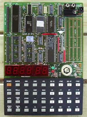
I have been trying to troubleshoot a CSQ-600 received in very poor condition and obviously broken down for some time now. I found the few defective components and repaired the tracks interrupted by the backup battery acid. However, I can't get the machine to start. When I look at the signals from the processor on the oscilloscope, nothing happens.

So I assumed the CPU was down. I ordered a new component already programmed and saw the same type of behavior. In order to try to find out more, I mounted a tester of 8048 and 8748:

Using this assembly, I could see that reading both processors gave me the same memory dump, which bothers me a little since in fact, I can't find the beginning of a failure reason. So for fun, I passed the dump to the disassembler and got an ASM source.

Obviously, a quick look showed me that there was a problem:

In fact, this code can never be reached because there is a 'RET' before it and obviously no other part of the code points to 'inc @r0'. 

I passed the dump in several disassemblers always obtaining the same result. From what I understand, neither the timer interrupt nor the INT interrupt are used in the CSQ-600 system. This is a program that runs continuously with reroutings depending on the positioning of certain flags including that of the INT input and that of the timer. The addresses concerned, 0x0003 and 0x0007 for IRQ & TIMER IRQ therefore do not contain a jump instruction.

I must say that with the simulator, some ports change their state at the rate of time elapsed by the timer. However, during my tests on the machine, I do not see any change in the state of the ports. So maybe it happens very quickly when the machine starts up (this is what I seem to have noticed with the logic analyzer), then afterwards, the processor goes into a loop and then nothing moves. Which does not tell me why the processor get into this state. I tried to change the state of the pins associated with a flag to see if that unblocked the situation but, again, nothing happened!

I passed the assembly code in a DOS simulator and as soon as I assembled, I did get an error:

This error is positioned on the line 'djnz     r5,L02AC'. So I am not able to know if the generated ASM source is correct or maybe the memory dump is not correct. Since I don't have the original CSQ-600 processor binary file, after all my investigations I am unable to determine what the problem might be.

I'm not going to start disassembling the CSQ system by hand. So I decided to stop my investigations there. I will instead develop a small STM32 processor board which will replace the original processor. This will allow me to spend some 'pleasant time' operating the hardware parts of this machine and perhaps developing a complete system...

To be continued...

DRUMULATOR :

A few months ago, I bought a broken Drumulator. The objective was to use it to test the realization of the wave sequencer in FPGA:

The tests having been conclusive, I decided to completely reassemble the machine by fixing the various remaining problems. Once done, I realized that there was a power problem.

In fact, the regulator hidden under the black cover is defective. So I had to remove this component from the metal base of the Drumulator:


I discovered an SH323SC from Fairchild. On the other hand, I could see that the original regulator had therefore already been replaced. I decided to place an LT1083 that I have in stock.

Also, since the Drumulators Reset circuit is often a problem, I will implement my replacement board with auto-saved RAM. This will be more reliable than the original system.

It's quite incredible to see the 'shitty' tweaks that can sometimes be done on the machines. This Drumulator collected quite a few!

To be continued...

CNC:

A few days ago, I finally finalized the settings and operation of my little CNC. So I ordered and received the accessories needed to cut plastic and aluminum:

Obviously, when you don't know anything about it, you make order errors. It must be said that the explanations that can be found on the sites of certain retailers are, how to say, quite vague. 

So I ordered two Collet Chucks suitable for a chuck much much larger than that of my CNC. Reference misinterpretation on my part. But hey, the second order was the right one :-)

I just have to find and test the software that will allow me to make the cuts I want to make. I have a feeling it won't be easy... 

To be continued...

vendredi 20 mai 2022

CSQ-600.

 A few years ago, I acquired a Roland CSQ-600 sequencer in very poor condition and downright out of order.


I have been troubleshooting this machine for some time. After some investigation I have only found one broken LED so far. 

However, I still find it completely impossible to start the CSQ-600. On the oscilloscope, the processor seems totally frozen. No scanning is performed on the buttons for example. So I suspected a problem with the processor.

I therefore bought on eBay a new processor equipped with the correct firmware. After replacing the old processor with the new one, the result is the same. The CSQ does not start.

So I wondered if the processor bought on eBay was indeed well programmed. But how do you know?

After some research, I discovered that someone had developed a small board capable of programming and reading this type of CPU.


All the information for the realization of this board is available here. So I made a copy of this programmer. The author has slightly modified the layout of the components but the operation remains the same. 

This material is used with a small software allowing to read and program a certain number of old circuits of which the 8048.


So I performed a memory dump of the two processors, the original one, and the one bought on eBay. What was the result?


Well the dump of these two circuits is strictly identical.

However, I noticed a rather strange phenomenon. After a few tens of seconds, the original 8048 of the CSQ-600 gave absolutely anything during new dumps.

While researching CSQ-600 troubleshooting info, I had occasion to read comments that the processor seemed to have this kind of problem. That is to say that when it was powered, a few tens of seconds later, the dump began to 'spin'.

I performed the test myself by cooling down the CPU and then testing it again. Indeed, after a few tens of seconds, the dump is no longer valid.

Ok, I've made some progress on the subject but... that still doesn't tell me why the CSQ-600 won't start!!! I got a disassembler, so I'm going to study the ASM source to see if the CPU does any test before starting the application. I will also try to test its start cycle with the logic analyzer.

What seems obvious now is that it is useless to perform these tests with the original processor. It definitely looks faulty!

And in fact, I also now own the binary code of the processor....

mercredi 18 mai 2022

Gowin FPGA

 I just received the PCBs for testing the Gowin 144 pin FPGA :

Yes, seen like that, it's not very 'sexy'. But hey, it will be, I hope...

lundi 16 mai 2022

The problem of front panel prototyping.

With the development of my MIDI switch, I am as always confronted with the mechanical realization of the case. The problem is that I have made good progress in the development of the MIDI switch and I would like to put it in a box. It would be much easier to develop the software, rather than having a whole bunch of modules on the workbench.

But it is not at all easy to find a manufacturer able to produce a front panel at an acceptable cost. In fact, I never found one. 

So, I decided to see if I could use the CNC that I own but have never used. I have owned this Colinbus since 2007, following an article by Elektor :


In fact, for lots of reasons, I never assembled this machine until 2016 or 2017, I'm not sure, where I started assembling it. And then I found myself confronted with the problem of the electronic control board. It was a proprietary board, so you had to get the proprietary software, which I couldn't do. 

It must be said that this machine was no longer offered for a long time and that its electronic board was no longer able to communicate with the manufacturer's current software. So I decided to switch to a more current and above all more standard control board, I opted for a TinyG board from Synthetos :


And, in 2020, thanks to the first confinement in France, I took the opportunity to finalize the assembly of the machine with this new control board I wrote an article about it in French here. I was able to test the machine with the new board, as well as control software whose name I no longer remember. 

But it wasn't working correctly. the X and Y movements were unable to realize the extent of their theoretical displacement. 

Despite a whole series of tests, I was not able to find the cause of this malfunction. I assumed then that it was either the software, or the power of the laptop used, or mechanical alignment problems that prevented the correct operation of the CNC.

I dropped the case again until a few days ago. It must be said that I am really motivated to create a correct front panel for my MIDI switch. This time I used CNCjs. And I also changed the USB cable that I originally installed in the CNC :


And then, I don't know why, everything started working fine. I was able to move all three axes with no problem. The use of the keys of the keyboard for that allows precise and fast test. The only small problem is that I found that the machine generated a lot of extraneous noise, some of which seemed to me to resonate. Which is not good for the precision of the machine.

But, after having checked and perfected the tightening of all the screws of the machine, these parasitic noises have disappeared. So it looks like I am now able to perform drill tests with this machine. I still have to find suitable end mills as well collet chuck for the milling motor. 

Because when ordering the machine, I also asked for a slightly more serious motor than the original one, but was obviously delivered without collet chuck : Optionnal :-(

In short, fifteen years later it seems to me that I have never been so close to finally using this CNC. Hoping that the final precision is correct, even if for my work on the front panel I don't need great precision. 

The CNC, once well adjusted and tested with CNCjs: