jeudi 10 juin 2021

New PSU for the PROPHET-VS

 The Sequential Circuits Prophet VS is a great synthesizer :


But it is also a machine that is not very well made. Poor quality components, perfectible printed circuits, spreading out of the processor buses inside the device, a PSU that heats up a lot, a very noisy transformer and above all a whole series of very poor quality connectors. Not to mention the 'famous' CEM5530 whose production at the time must be completely out of service today, reason why I had to develop a replacement clone years ago.

The copy I own has only really worked for a few years, after making a lot of changes. And yet, there would be more to do. And precisely, one of the really painful things in this machine, when it works and that one can use it, it is the very important noise which the power transformer generates: very boring.

So, I decided to replace the whole power system of this VS. There were several possible choices for creating a replacement PSU. I decided to create a generic power supply that can be used in other devices, and secure, without handling high voltages. 

I created a low voltage switching power supply with linear regulators on the + 12V and -12V outputs:

Beta version.

Output technical details:

  • +5V     2A (switching)
  • +12V   2A (switching + linear)
  • -12V    2A (switching + linear)
  • RESET signal
  • /RESET signal
  • +5V     BATTERY
  • Power Error indicator
  • Floppy type power connector
Input technical details:
  • 2 x 18V/AC
  • Thermal fuses
Advantages:
  • Precise outputs
  • Low heat dissipation in normal use

I have to admit that it took me several versions to sort out the little issues that I encountered and thus obtain a very reliable and convenient power supply. To install this new PSU, the first thing to do was to remove all the concerned components on the Prophet motherboard:


In my case, I also removed the memory backup battery because I equipped my Prophet with self-backed SRAMs. This avoids any possibility of problem due to a possible corrosion of the battery body which could cause serious damage to the printed circuit:


The components removed from the Prophet motherboard:


'Last' modification, I placed wires for + 5V, + 12V and -12V, intended to be connected to the new PSU:


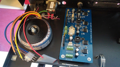
After that, it only remained to place the new power supply into the Prophet, as well as the new transformer:


Regarding my VS, I saccrified the voltage selector and shortened it to be able to position the new PSU more easily. I obviously kept the fuse holder that I put in place of the voltage selector.

During my first operational tests, I observed some problems with the sound. The red LED on the PSU would light up at times, indicating a loss of regulation. It was normal since I did not have a 2x18V transformer available but only a 2x12V. The + 12V and -12V regulations could therefore not be provided correctly. 

So I ordered and received a few days later a German quality 2x18V transformer. In the meantime I also made the last modifications on the printed circuit of the PSU and mounted this new copy in the VS:


Self congratulation but... I am very satisfied with the result. The PSU works perfectly well. The error LED remains constantly off. The PSU heats up very moderately. Above all, the Prophet no longer emits any operating noise. And that is a real pleasure!

Exterior view:


Funny: the three green LEDs of the PSU illuminate the printed circuit board of the front face, which has the effect of nimbling the 'Enter' and 'Edit Waveform' switches with a green hallo.

If you are interested, this PSU is available. Contact me for more information:

mardi 18 mai 2021

Retro computing µPF--2, the first real start.

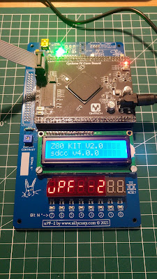
The implementation of the peripherals being different on this board, I had to modify the VHDL code of the system that was working on the generic FPGA board. It took me much less time than I expected to achieve a functional result:


For the moment I have only tested the displays. The next step will consist of checking the operation of the USB serial com port as well as the communication with the keyboard. But for now, the new µPF--2 board will be able to replace the generic FPGA board on my desk and it feels good because it's been a few months now since I started porting µPF--1 to an FPGA board:


jeudi 13 mai 2021

OMEGA MSX COMPUTER : A USB keyboard converter

I am currently very busy developing the µPF--2 kit. However, I continue other development in parallel, including a USB keyboard converter for the MSX Omega computer:


More information here.

mercredi 12 mai 2021

Retro computing : µPF--2, a µPF--1 clone.

The project to recreate the µPF--1 kit is progressing. I now have a complete hardware system that will allow me to implement the FPGA code emulating the µPF--1:


More info here!


lundi 10 mai 2021

µPF--2 : The printed circuit board

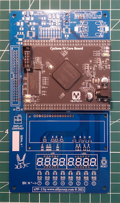
 I like to receive the printed circuit board of a study. This makes tangible what was then only a concept :


Everything looks fine. Even the FPGA module sits correctly!

In fact, it is sometimes quite curious to see the result of an idea that we had formed a few months earlier. I didn't think the final design would look like this.

It only remains to build the circuit step by step, hoping to avoid the 'magic smoke'...


jeudi 29 avril 2021

µPF--2 : Final Beta Version

By reworking the layout of the components, I finally had enough room to implement all of the extension connector signals. All I have to do now is to create the printed circuit board:


The final circuit is quite large in the end, given all the elements that are implemented.

Eventually, I hope to be able to operate these various original expansion boards knowing that they are intended for a µPF1P and not a µPF1 or 1B :

Printer & I/O boards.

Interesting informations on this subject are available on this site: https://fjkraan.home.xs4all.nl/comp/mpf1/


jeudi 22 avril 2021

µPF--2 : Finally it should look like this!

As I mentioned in a previous post, it is not always easy to arbitrate between the capacities of a system and the difficulty of its material realization, especially if in addition the final price must be as tight as possible.

For this uPF--2 I considered several possibilities before arriving at a system which I believe to be sufficiently simple but efficient for the envisaged use.

Here in 3D what should look like the system :


Due to the FPGA used, I reduced the expansion bus to only addressing peripherals. This should be more than enough to create I / O expansion boards of all kinds.

This system takes all the characteristics of the original board of Wichit Schirichotte, but largely improved in terms of capacities and speed of execution.

http://www.kswichit.com/Z80/Z80.html