vendredi 27 septembre 2024

Drumulator and Efinix FPGA

I haven't posted in a month now. It was back to work, and then I worked on the startup of the Drumulator system in an Efinix FPGA.

I made good progress and managed to start the Drumulator system. However, I'm getting some pretty strange results on the screen that I get when debugging the VHDL source.

So, as I find that I am no longer making progress on the subject, I am going to develop a small display interface that I will plug into the fpga card in order to see what I obtain.

And then, there are subjects that you can carry around for years without ever succeeding in really finalizing the concept. A few months ago, a few years now, I developed a sort of MIDI switch. The idea is good, but in fact, when I found myself in front of my stack of synths these last few days, I realized that, in reality, no, the notion of switch is not the right one at all. And I don't know why, but a kind of 'revelation' came to me. And it's completely crazy, because it goes against what I've been trying to do for years. I'm going to tackle this topic.

Regarding the MSX cartridge that I developed over several months, I can say that the cartridge works very well on my Omega. Unfortunately, it does not work well on a Panasonic without me being able to determine the reason. So as I don't have MSX machines of different models and as it's difficult for me to get help on this one, I decided to stop my 'waste of time' on this subject.

That's all for now.

mardi 27 août 2024

TC Fireworx

There are times like this when machines come to me almost in groups for repairs. I just got a TC Fireworx and a DP4+ Ensoniq. I'm starting with the TC:


This is a classic digital multi-effects from the late 1990s, early 2000s.

The machine does not start anymore. This effect rack does not seem to be a killer in the sound grain, but hey, I imagine that it must still provide good basic effects. After opening it, we see that the machine is well made. Well thought out too. There are however quite a few small connection retakes on the top of the board. In my opinion they are original. There must have been some modifications after the board was produced.


First thing to do, power up the machine. This should go well since there is no smoke or hot spot on the motherboard, and the power supply fuse is not blown.


On the other hand, in my opinion, the principle of connecting the power supply to the motherboard is a bit of a stain on the board. Why not have put real connectors? It is therefore mandatory to remove the motherboard from the machine to be able to unsolder the wires connecting to the power supply: not great!

It is also not practical to connect another power supply to it, for this it is necessary to solder the wires of the new power supply. Then unsolder them when the tests are finished: hum....

The voltage tests carried out at this time give me +26V and -26V for the analog part, knowing that I took the analog ground as a reference. This does not seem good to me at all, but I will see later. On the other hand, the +5V gives me 0V. Compared to the behavior of the machine, this seems consistent to me! At first glance, the power supply seems to pose real problems.

Fortunately, the machine is small and removing all the insides is not complicated and does not take too long.


So the next operation was to unsolder the power cables and power up this power supply without load.

I spent some time testing the operation of all the diodes and transistors before actually powering up this power supply. Having noticed nothing suspicious, I started it up. The output voltages are still +26V and -26V, but I now get the +5V dedicated to the digital part. This is better. This most certainly indicates a problem with the capacitors on the low voltage output. This power supply is so compact that you can't see at all what's happening between the components. So I decided to unsolder one of the two large capacitors, I started with the easiest to remove.

I was not disappointed with the result. Look at this 'battlefield'!


And of course, the first 'death':


But look at this!!! I have never seen a capacitor in this condition. Even low-end capacitors never gave me such a result: incredible! And yet, it is a branded capacitor!

First step. Before continuing on this power supply, I will connect the motherboard of the device to a laboratory power supply to check if it starts correctly and if the analog part works. Because with the overvoltage that I see at the output of the power supply, I still have some doubts. It would be a shame to waste my time on the power supply if the motherboard is defective because it will most certainly be irreparable.

The next step was to install terminal blocks on the motherboard of this machine, so that it was not necessary to desolder and resolder the power wires a 'number of times'.

Then turn on the machine.


A tentative conclusion: the machine starts and seems to work correctly.

However, a doubt remains. Indeed, during my first tests, I measured an analog voltage almost twice what it should be when the board was connected to the original power supply. So I don't know how much this could have affected the operation of the operational amplifiers if this voltage was actually applied when starting the machine.

Fortunately, all the digital/analog and analog/digital conversion circuits are supplied with +5V, the regulator providing this voltage on the motherboard obviously having no problem providing this +5V, I can assume that these conversion circuits are still operational.

Starting the machine with a laboratory power supply :


I just have to test the audio system before switching back to the original power supply.

The 'problem' is that all the connections on this machine are XLR. And, although I have XLR/JACK cables, I don't have any XLR/XLR ones. So a small purchase and my very first XLR machine connection : 


After connecting a synthesizer directly to this Fireworx and connecting this Fireworx to my PC, the observation was very simple: it works very well.

At least I'm sure that the malfunction of the machine's switching power supply did not cause a problem on the electronic board.

After cleaning the power supply to remove all the residue due to the leakage of one of the capacitors, I started looking for replacement capacitors. In fact, I decided to replace absolutely all the chemicals in the secondary. The large filter capacitor in the primary still has a good capacity, and shows no signs of leakage. I left it in place.

It was not as easy as expected to find the right capacitors. The ones originally used are very small. So I had to 'trade' the small diameter for a larger height of the new capacitors. I finally found models that were quite suitable.

Which allowed me to finally carry out the first tests of the machine with its original power supply as shown in the previous photo.

Note that testing this power supply is not very practical. Indeed, there is a whole standby system that does not allow you to check the 'relevance' of the 5V. I was still able to see that the 22V voltage of the power supply originally, had dropped to a voltage of 16.5V, i.e. +16.5V and -16.5V. It was already better. The problem is that during my first tests, I had modified the 5V adjustment trimmer, and now that the power supply was in principle repaired, I had no idea what this voltage could be.

Fortunately, it is enough to test the voltage provided by the standby mode 'output' system (brown wire), it must be 5V, which I adjusted using the trimmer. Once this adjustment was completed, all that was left to do was to connect this power supply to the motherboard of the machine, and check the overall operation. The results were therefore conclusive, with this time +14.8V and -14.8V in charge for the analog power supply and a nice 5V for the digital part.

And now? Back in the box!


I was able to do some audio tests with this machine. The opinions that I was able to glean on the Internet are rather mixed about it. They indicate that the sound quality and the treatments are not exceptional. I find that it works very well. Afterwards, some effects can be questionable, especially those dedicated to the treatment of guitars, you have to have the use for them, but otherwise....

For a 25-year-old machine with exemplary construction (except for the power supply which is clearly not top of the range), and at a purchase price of around $800 in 1998, it is still a good machine today.


lundi 19 août 2024

TI59

Sometimes unexpected encounters happen. This time with a TI59 and its PC-100C printer.

In fact, a few days ago I was walking in a square somewhere in Brussels, where a garage sale was taking place.


And, while walking through the maze of pop-up shops, I come across a TI59 installed on its PC-100C printer.

wikimedia.org

A few days later, during a break in my vacation wanderings, I couldn't resist the urge to test the set in my hotel room. After checking that the machine's fuse was in good condition, I tried connecting the PC-100C to the mains. And there: 'magic smoke' :-(

I suspected it a little. I wasn't too disappointed though, knowing that I bought the whole thing for €5, sold by someone who obviously knew nothing about it, and presented as an old cash register!

After a relaxing vacation and back home, I took the printer apart and discovered what I expected, namely a nice 'burned' tantalum capacitor.


This type of capacitor is quite annoying in the long term because it tends to generate a short circuit one day or another. And that's what happened. The capacitor was therefore completely destroyed, and this was the reason for the destruction of the protection fuse.


I therefore changed all of the capacitors of this type with good quality chemical versions. I won't have any more problems like this for a while.

And then I took the opportunity to inspect the electronic card of this printer a little more. Because I still found it a little strange that the recovered set was in such good condition. In fact, there are just the keys of the TI59 which are no longer very good on the surface. I assume the foam must be completely disintegrated.

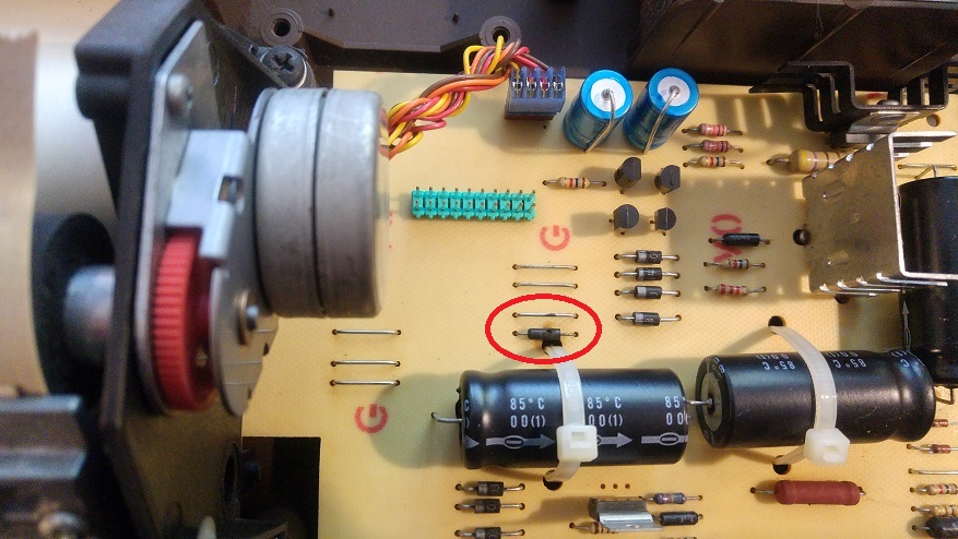
And here is what I discovered:


And there you have it: two beautiful welds which are not original and which I discovered. Nothing serious at the moment, but this could indicate that the entire system was having operating problems. And therefore, it would not be impossible that despite my repair, the system still does not work.

And it is. Once you have reassembled the PC-100C and placed the TI59 on its support, of course, the red printer LED lights up, but nothing happens to the TI59. I don't even hear the little characteristic noise of the voltage booster module, such as I heard on my TI57... at the time. However, the printer does deliver -3.75V on its connector, to the 59.

Nothing happens to the printer either. Even the paper advance doesn't work. At this stage I haven't read the instructions manual, but I imagine that paper loading 'should' still be possible. It doesn't matter right now. First of all, and since it is the calculator which is the center of this system, I decide to look at it first. Fortunately I was able to find the diagram of the 59 and the PC100 on the Internet.

So at this point the next objective is to check what happens if I apply adequate voltage to the calculator and thus, I hope, determine where it is stuck. The first thing to do is to disassemble the TI59. Hmm... bad memories of my TI57 encourage me to be extremely careful. A broken plastic lug holding the keyboard, and it's ruined! No need to think about replacing it or regluing it: it doesn't hold, even with glue!

First operation, at risk, disassemble the TI59 without breaking anything! I achieved it :

The motherboard

Displays & keyboard

What I was thinking about the keyboard, namely that certain keys no longer rise correctly to the surface of the machine, actually comes from the fact that the foam which is supposed to place the keys towards the surface of the calculator, is in very poor condition :


And I didn't break any of the four lugs holding the keyboard/electronic card assembly in the body of the machine!

The first tests of connecting the machine to a voltage source of 3.75V gave me rather worrying results. I discovered consumption much higher than expected. After testing the capacitors and diodes on the board, I don't find anything special. This is even more worrying. And, of course, the machine won't start.

At this stage, I still have to discriminate whether it is the module which generates the two negative voltages -Vdd and -Vgg which poses a problem, or whether it is 'behind' that this is happening. So I need to remove this module from the TI59 card:


Powering up the machine does not generate significant consumption, knowing that without the module, only the -Vb voltage (the supply voltage of the machine in fact) is used. There is therefore no consumption on -Vdd and -Vgg :


I power the calculator at a little more than 3.7V knowing that I go through the power supply diodes. 

Consumption is very low. Normal since I think none of the machine's circuits are working since they all use the other two voltages which are not present at the moment. I don't know how the logic circuits support this power condition anyway, but I don't really have a choice.

I therefore also checked the operation of the module which generates the two negative voltages -Vdd and -Vgg. I also obtain an idle consumption of only a few mA. The measured output voltages are -9V for -Vdd and -12V for -Vgg. This should be -15V for -Vgg but hey, that's not the topic at the moment.

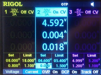
Following these operations, I reassembled the module for testing the two negative voltages and turned the machine back on. The result was immediate with an overall consumption of almost 200mA. Something really unusual is happening. I know, however, that this is not on the -Vb and that the voltage module is not the cause either. I still have to check -Vdd and -Vgg.


While I still have -12V for -Vgg , I now find myself with -6V for -Vdd. I'm starting to better understand the problem with -Vdd. However, all integrated components use the three voltages. For discriminated against, well it’s relatively simple. Given that I have excessive current consumption, I then necessarily have a component which consumes this current and which therefore heats up.

So I decided to let the calculator 'warm up' for a few minutes. And indeed, after a certain time, I detected a component which was heating up while all the others remained cold.


The TMC0583 is clearly hot. It is therefore very likely that the problem with this ti59 comes from this component. However, I am not 100% sure because it is fixed on the TCM0582 which may also present a problem. The only way to check if my idea is the right one is to desolder and remove this TCM0583.

But in any case, and in accordance with the calculator diagram, if the TCM0582 or the TCM0583 is out of order, there can no longer be a display. Additionally, these two circuits contain the system ROM, so the calculator almost certainly cannot even boot anyway.


If my theory is confirmed, it will then be very difficult for me to restart this machine. It is not possible to find this type of component, even second-hand. I would then have to find a defective TI59 and try to recover the necessary component, provided that it is functional of course...

I was wrong all along, and here's why...

Following previous experiments, I decided to remove one of the components of the calculator, namely the TMC0583 because I found that it was hotter than the other components. 


I find myself with a lower consumption of only 30mA compared to the consumption of the machine equipped with this TMC0583. 

In the event of too high consumption of the calculator, this component is therefore not the main source of consumption. The doubt about the idea I have of the dysfunction grows. On the other hand, and interestingly, I leave the machine powered on for a certain time in order to control the temperature of the components.

After about 15 minutes, I realize that the temperature of the TMC0582, the component on which the TMC0583 is soldered, is also hot, but actually no hotter than the TMC0583. So I'm starting to think that potentially there are no defective components. But then, why doesn't the TI59 start?

In this case, I only see one reason: the conditions for starting the machine are not met. However, until now I have carried out the tests with the magnetic card reader removed. So I decide to reconnect this card reader. And what do you think happened?


Well yes, the machine starts. The card reader is under the sheet of paper to avoid possible short circuit. Note that at this precise moment, I did not put the TCM0583 back in place.

The machine functions normally, it recognizes Pi, but is unable to perform any mathematical operation whatsoever. Indeed, the code for the mathematical routines must be found in this TCM0583. It's quite 'amusing' to note that the absence of this ROM of mathematical functions does not absolutely crash the machine. The order is simply not fulfilled : cool!

Needless to say here, I think (but I do it anyway), that I am very happy with the result. I therefore decide to put the TCM0583 circuit back in place. Once the operation is completed, I switch to around 200mA consumption without using the card reader. This consumption varies depending on the number of digits lit on the display.


Now for tension control. Warning, the reference of the two negative voltages Vdd and Vgg must not be the ground, but in fact the positive power supply of the machine, therefore not -Vb (corresponding to the ground of the power supply supplied to the calculator) but the positive pole of this power supply. And as -Vb is equal to approximately -3.3V, we end up with -Vgg not at -12V, but -15V, and -Vdd not at -6V but at approximately -9V.

In reality, I measured not -9V for -Vdd but -8V real. Vgg being really at -15V. In short, all voltages seem good and consumption is stable at around 200mA.

After more than an hour of operation, all the measurements have not changed, a sign that everything is working. I was even able to enter a small program and run it. I hadn't done this kind of thing since I got rid of my TI57, 6 or 7 years (1988~1989) after buying it because the keyboard had become unusable. I tested a good number of keys on this TI59, the keyboard seems to be in good condition.

I obviously don't have much left to do on this calculator. I placed a solder spot on each expansion module connector tab. While wanting to test the voltages on this connector, one of the legs became detached from the card. I had to solder it.


Conclusion: I don't have an answer to why the calculator wouldn't start. However, I opt for a small contact problem on the flexible cables which connect the card reader to the calculator. However, these connectors firmly hold the tabs on the flexible cables. During my tests, I connected the power supply to the terminals of the blue power filter capacitor present at the bottom left of the TI card. Since then, I have connected the power supply directly to the dedicated pins of the machine by increasing the supplied voltage by 1.4V and everything works perfectly. I did not power the machine through its battery connector, I still have this test to carry out.

Would I have put this machine back into operation faster with the documentation? I don't know. Concerning the tensions, I did not see any mention of what the reference was. It is also not explicitly written that the card reader must be connected to the machine for it to start. 'Worse', while reading the documentation I let myself be 'influenced' by the troubleshooting advice stipulating that if nothing happens, then look at the TCM0583.

But hey, I didn't spend too much time on the machine, just over two hours. Everything is not finalized however. I still have to find a suitable foam to put on the keyboard before reassembling the machine. And I will also need to test the communication with the printer.


mardi 23 juillet 2024

Trion FPGAs

Getting started with the Trion FPGA.

For the past few days, I have been trying to operate a minimal Z80 system with the aim of implementing the entire logic part of the Drumulator in a TRION type FPGA.

I will spare you the details of the necessary 'acclimatization' to a new development environment, both hardware and software. As far as I am concerned, this stage is always long and tedious for me, which is why I have never been 'pushed to study', as they say back home. (This is not the only reason, but it is 'technically', the main pretext used for exclusion from the French school system).

So, it is absolutely necessary for me to understand what I am doing. I started from the base, namely a system just capable of producing the 'famous' Hello World of electronics, namely, the flashing of LEDs. A small 'complaint' on the Efinix dev board, it does not include the minimum amount of hardware capable of producing an 'intelligent' display. No digital displays, nor LCD: too bad. You must therefore make do with the 8 basic LEDs present on the circuit.

I will therefore reproduce the animation, but with only one LED lit at a time', supplied as a demo program with the board.

In order to test the concept a little in depth, I decided to implement the LED output register as a memory register AND standard IO type output. So I produced a 'quick & dirty' conditional code allowing me to test both implementations.

(the code of death)

Regarding the equivalent VHDL code to select the LED output either in memory register mode or in out mode in the I/O zone, simply modify the code selecting the LED output register like this:


Not very complicated either!

Oh good? And several days for that? Absolutely. I had made some clock synchronization errors which meant that at the default speed, high clock speed, the system could not operate. Obviously, I then had to carry out debugging by testing the entire operating chain of such a minimum system. I could have used internal debugging, but I have to say that the Efinity development software is not really well integrated. It does not offer a signal shape viewer like GTK WAVE to display the result of an execution. In a nutshell, I didn't want to spend time trying to get difficult-to-install external free tools to work. I could also have used the I/O ports on the dev board and plugged in a logic analyzer. I have a logic analyzer on PC, but I really don't like its interface at all. And overall, I support these Windows-based systems less and less.

Additionally, I also 'wasted' time trying to figure out the file format needed to fill the BRAM area used in ROM with the 'C' code binary. In fact, the file to produce is much simpler than the Efinix documentation suggests. As is often the case, they explain the internal workings of filling the BRAM, while taking care not to correlate the explanation with a real example. So, it's pretty easy to understand how this is supposed to work internally, but gives absolutely no information about how it relates to the real world. So, it's quite complicated to understand how to simply present the binary file. The typical kind of documentation provided by Microsoft: drowning the person looking for it under a mountain of doc that ultimately has nothing to do with the question. The result is simple, the graphical interfaces supplied with small development systems are no longer updated, or work in Windows 7 mode, as long as it works. Microsoft had already 'gunned' the small structures which provided even professional software solutions in DOS and Basic, at the beginning of the 90s. Microsoft is now euthanizing all the medium structures which still work (or still try to do so) with Windows. Great!

In the end: I obviously managed to make this minimal system based on Z80 work. The Efinity software also tells me that I can potentially make it work at more than 60MHz. So I tried to power all the logic directly with the 50MHz oscillator placed on the test board, and indeed, the result is completely functional.


A few seconds of illustration of how this first test works:


vendredi 12 juillet 2024

Trion FPGAs

And meanwhile...
I am testing new FPGAs, in this case the TRION family from Efinix.

Why venture into other FPGAs, when I have already worked with those from Altera (now Intel) and those from GoWin? Mainly for a question of cost and availability of 'small' footprints.

I really started testing the development chain only a few days ago and I must say that I am progressing quickly and easily. I had already studied the entire processor part of the Drumulator drum machine a few years ago. I implemented this part in Altera FPGAs, then GoWin in 2020, but I stopped this subject because of the shortage of components, then subsequently, the very significant increase in component prices, particularly that of FPGAs GoWin, which more than doubled.

And then, I recently discovered FPGAs from the Efinix brand and in particular the Trion family of FPGAs. Given the price of these circuits, I decided to resume studying the Drumulator. For this, I acquired a basic development board :


After installing the Efinity development software, I set about transcribing my VHDL source code to this new development tool. Its handling is not at all complicated and resembles the development software of other FPGA manufacturers, although simpler.


Although all windows can be floating, when you have a screen of sufficient size, the most practical thing is to have them all in the same window. The window 'modality' system used by Efinix can sometimes be quite annoying.

Nothing special for those who have a little mastery of VHDL, a language that I use mainly for writing code. The development board only contains a minimalist 'user' interface. A few LEDs and a few switches and that's it. It has no displays at all. So, it becomes a little complicated to test my Drumulator source. So I coded a driver allowing it to be sent to a serial interface, what the Drumulator should normally display on its four digits.

After some trial and error with the Efinity development software, I ended up obtaining a complete compilation of my source. All that remained was to test it on the development board.

But before that, you must install the USB drivers allowing programming of the FPGA. In fact, it is necessary to use the Zadig configurator in order to configure the two interfaces offered by the development board. The SPI interface and the JTAG interface.


'As they say', there is no reason why the installation of USB drivers should not work. And, normally, we must actually get the two drivers installed in the system.


At this stage, all that remains is to program the board with the generated code. For my first tests, I use JTAG programming, which allows the FPGA configuration memory to be directly programmed without touching the SPI interface and therefore without modifying the external configuration EEPROM. This allows you to find the demo code present when the board was delivered and therefore to check that it still works. We never know...


And there you have it, the whole procedure went well. Firstly, as I did not connect anything to the development board, I simply activated part of the LEDs with the memory zone selection signals, as well as creating, but externally to the Drumulator system, a low frequency blink clock for an LED. This will allow me to verify that at least the entire development.programming chain is functional, the traditional Hello World, in a way.


I developed a small expansion for the development board. The idea is to be able to test digital audio using boards recovered from an Akai digital recorder, as well as to test an HDMI type video output. These two topics are based on LVDS transmitters/receivers.

Otherwise, we can clearly see that the 'left' LEDs are lit. In fact, if you look closely, you can see that the one on the far left is slightly less bright than the others. This suits me well, this LED corresponds to access to the ROM of the Drumulator. It is therefore the most frequent access, which therefore represents a more intermittent ignition time, and therefore lower brightness.

And, what can't be seen in the picture, the LED on the far right is blinking slowly, indicating that the entire development chain is working.

Provisional conclusion: I am now sure that the entire development chain works, as well as the programming system of the development board. I also have strong presumptions about the functioning of the Drumulator core in this FPGA. I still have to connect a USB/serial adapter to my computer to check that I am receiving something when the board starts up.

I haven't coded the conversion of Drumulator segment type data to its ASCII character equivalent, so if it works, I will potentially receive anything, maybe even non-printable characters. It doesn't matter for the moment, the goal is already to see communication. And then it will be quite difficult to display anything else, given that I have not yet connected any switches to the heart of the  'Drumulator', I will not be able to generate any other information transmission. But hey, everything in its time...

lundi 1 juillet 2024

Just for fun?

It's been two to three years since I fully understood the 'democratic' operating (or dysfunctional) system of France. I know for example that, given my social class of origin which is totally foreign to the French bourgeoisie, and the way in which the oligarchy (the upper French bourgeois classes in power) has made the creation and exploitation of a viable business in France totally impossible for people not from the bourgeoisie, I know that it is totally impossible for me to 'succeed' professionally both as an employee and as an independent. This situation, absurd if we consider the collective aspect, leads to the economic results of France today as well as the result in the 2024 municipal elections in favor of the National Rally.

For decades I had felt that something was wrong in this country, but hey, to understand, you have to 'politicize' yourself. Which was not the case for me until recently.

Brief! However, it has been a very long time since I realized that what I was asked to do, within the framework of a job, did not correspond at all, neither to my real skills, nor to my desires. Reasons why I have always developed electronic projects privately. Lately I have even tried to insert myself into topics trying to promote my achievements and possibly market them. In vain. On this subject, however, I haven't really managed to understand yet. I have an idea, but I'm not sure.

By developing small electronic systems, I acquired some small skills. I am therefore going to implement them in what was my childhood dream: creating electronic devices dedicated to music. I have in stock an 8-way CV/GATE interface to be finished, as well as a MIDI connection system a little more adequate than the current MIDI network to be finished. So I'm going to devote myself to it.

And, since I have just repaired a Drumulator again, I like this machine and I have already prototyped pieces of it, I will start by trying to create a complete clone. I will put the progress of the project on this post.

Why the Drumulator?

My last repair dated 2024/06/30

Because it is a rather particular machine which, despite the theoretical simplicity of its operation, produces very good percussion sounds. This is because the sound production system is based on playing non-linear 8-bit samples. To simplify, it uses a particular coding that was used in analog telephone networks to artificially increase the audio quality of communications. Its 8-bit resolution thus increases to a 12-bit equivalent. Obviously, as the conversion cannot be linear, this gives a very 'punchy' but nevertheless very well defined rendering, perfect for percussive sounds.

Clone this machine, yes, but in a hardware way or in a software way?

In fact, I have already had the opportunity to develop the processor core of this machine in FPGA, as well as the wave sequencer. I did this on an Altera FPGA, then GoWin. I wanted to use Gowin FPGAs, but between the time I carried out my first tests and when I could have started producing a prototype, the price of Gowin FPGAs was multiplied by three!

At that time, about four five ago (2019), the price of a used, working Drumulator was around €250 in France. Which did not leave much room for the creation of a profitable machine from a financial point of view. The price of a Drumulator has now increased significantly, and is around  €700 ~ €800, leaving room for a clone.

https://fr.audiofanzine.com/bar/e-mu/Drumulator/

I also spotted FPGAs from another manufacturer whose characteristics are quite interesting and whose selling price corresponds to the development of equipment that must be sold at a reasonable price: the Trion family from Efinix


Obviously, moving from one FPGA family to another is not particularly trivial. Not because it involves changing the type of technology, but rather because it is 'yet' a leap into the unknown. When you 'habit' with a component, you navigate within your 'comfort zone'. Obviously, changing manufacturer means changing development software, physical constraints on the component itself, etc... We never do it lightly. But hey, at some point you have to go.

If I start this topic about an FPGA Drumulator, it's because I have already carried out some tests with the Efinity development software, from Efinix. And I know I can compile a complete Z80 system inside a Trion Fpga component.

But as of now, I have never actually programmed the study board I purchased.


For the moment, I have just implemented a Z80 core associated with the original Drumulator ROM in version 3.0. I have no means of display or input. I will therefore ensure that the message which should normally be displayed on the four digits of the Drumulator is displayed on my PC screen. To do this, I will just need to implement a system that translates the codes sent to the digit into a character string suitable for display on a terminal.

I will keep this principle subsequently, because I intend to dedicate the management of the front of the machine to a processor which will be connected by serial port to the FPGA.

So: attempt to activate the core of the Drumulator with display on the serial terminal of the 'famous' message "Bad"!

mardi 25 juin 2024

J'MSX : for the fun!

The weekend of June 23-24, 2024 took place in Paris, the meeting around the MSX standard:


the opportunity to meet around standard MSX and to compare our achievements with those of others.

I was also able to carry out some tests of my USB cartridge and found that it works well, except on the Panasonic FS-A1. The 48K cartridges seem not to want to launch after loading, although it works very well on my Omega and other machines.

So, I looked a little closer at this FS-A1 and noticed that its bios has some particularities which encourage some owners to replace it with a 'minimal' version. I will investigate this aspect, knowing that the cartridges which did not start on the Panasonic, work without problem on my Omega, without having touched it in the slightest, that is to say with the cartridge loaded with the ROM which did not start on the Panasonic!

Mr. Nishi was present at this MSX day. For those who don't know Mr. Nishi, he is the person who created the MSX standard with Mr Gates, in the early 80s.


No need to make introductions...


Mr. Nishi presented his MSX0 and MSX3 to us. 

So if I understood everything correctly, because I had never managed to understand what was going on since I saw articles on these machines, it would in fact be two machines based on the compiled MSX basic. Obviously these two machines offer an MSX compatible hardware environment, but based on an emulator.

Msx0 would be more specifically dedicated to IOT, while MSX3 would be adapted to computer learning. These two machines are therefore two somewhat dedicated hardware emulators based on a fast processor but I don't know what processor it is.

MSX0

MSX3

Well, until now I hadn't really understood the subject, and I was telling myself somewhere that I didn't really see the point of such a machine. Well now I know that these two machines are of absolutely no interest, sorry Mr. Nishi.

How to say, IOT is... dead! And learn computer science, in France, today, it's python, and that's all. so ok...

Nevertheless, I had the unspeakable honor of posing in the group photo with Mr. Nishi.

For me, the loop is complete. When I discovered microcomputers in the early 80s, people like Gates, Tramiel, Sinclair, Jobs, Woz and the others were simply geniuses and people living in a galaxy other than mine. I was fifteen years old and the future was just beautiful.

Obviously, since then, the reality here, in France, a small country with no future since a long time, my future has been completely different than the one imagined.

Come on, at least I feel like I was a little part of the story...


Those who know me will recognize me ;-)

Thanks to MSX Village for this very nice moment.