And meanwhile...
I am testing new FPGAs, in this case the TRION family from Efinix.
Why venture into other FPGAs, when I have already worked with those from Altera (now Intel) and those from GoWin? Mainly for a question of cost and availability of 'small' footprints.
I really started testing the development chain only a few days ago and I must say that I am progressing quickly and easily. I had already studied the entire processor part of the Drumulator drum machine a few years ago. I implemented this part in Altera FPGAs, then GoWin in 2020, but I stopped this subject because of the shortage of components, then subsequently, the very significant increase in component prices, particularly that of FPGAs GoWin, which more than doubled.
And then, I recently discovered FPGAs from the Efinix brand and in particular the Trion family of FPGAs. Given the price of these circuits, I decided to resume studying the Drumulator. For this, I acquired a basic development board :
After installing the Efinity development software, I set about transcribing my VHDL source code to this new development tool. Its handling is not at all complicated and resembles the development software of other FPGA manufacturers, although simpler.
Although all windows can be floating, when you have a screen of sufficient size, the most practical thing is to have them all in the same window. The window 'modality' system used by Efinix can sometimes be quite annoying.Nothing special for those who have a little mastery of VHDL, a language that I use mainly for writing code. The development board only contains a minimalist 'user' interface. A few LEDs and a few switches and that's it. It has no displays at all. So, it becomes a little complicated to test my Drumulator source. So I coded a driver allowing it to be sent to a serial interface, what the Drumulator should normally display on its four digits.
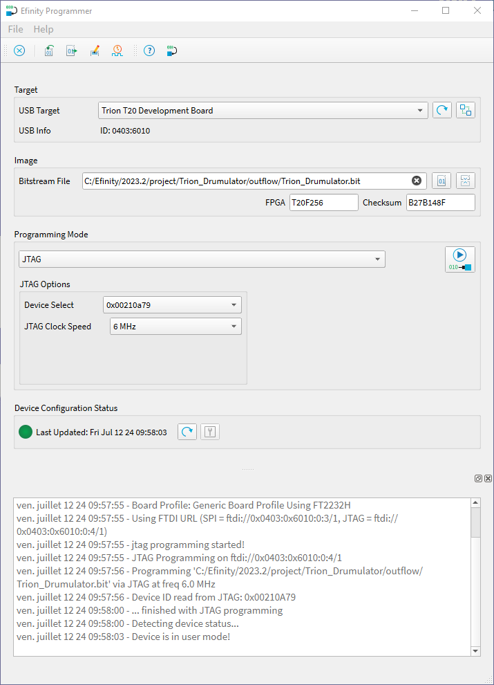
After some trial and error with the Efinity development software, I ended up obtaining a complete compilation of my source. All that remained was to test it on the development board.
But before that, you must install the USB drivers allowing programming of the FPGA. In fact, it is necessary to use the Zadig configurator in order to configure the two interfaces offered by the development board. The SPI interface and the JTAG interface.
'As they say', there is no reason why the installation of USB drivers should not work. And, normally, we must actually get the two drivers installed in the system.
At this stage, all that remains is to program the board with the generated code. For my first tests, I use JTAG programming, which allows the FPGA configuration memory to be directly programmed without touching the SPI interface and therefore without modifying the external configuration EEPROM. This allows you to find the demo code present when the board was delivered and therefore to check that it still works. We never know...
And there you have it, the whole procedure went well. Firstly, as I did not connect anything to the development board, I simply activated part of the LEDs with the memory zone selection signals, as well as creating, but externally to the Drumulator system, a low frequency blink clock for an LED. This will allow me to verify that at least the entire development.programming chain is functional, the traditional Hello World, in a way.
I developed a small expansion for the development board. The idea is to be able to test digital audio using boards recovered from an Akai digital recorder, as well as to test an HDMI type video output. These two topics are based on LVDS transmitters/receivers.
Otherwise, we can clearly see that the 'left' LEDs are lit. In fact, if you look closely, you can see that the one on the far left is slightly less bright than the others. This suits me well, this LED corresponds to access to the ROM of the Drumulator. It is therefore the most frequent access, which therefore represents a more intermittent ignition time, and therefore lower brightness.
And, what can't be seen in the picture, the LED on the far right is blinking slowly, indicating that the entire development chain is working.
Provisional conclusion: I am now sure that the entire development chain works, as well as the programming system of the development board. I also have strong presumptions about the functioning of the Drumulator core in this FPGA. I still have to connect a USB/serial adapter to my computer to check that I am receiving something when the board starts up.
I haven't coded the conversion of Drumulator segment type data to its ASCII character equivalent, so if it works, I will potentially receive anything, maybe even non-printable characters. It doesn't matter for the moment, the goal is already to see communication. And then it will be quite difficult to display anything else, given that I have not yet connected any switches to the heart of the 'Drumulator', I will not be able to generate any other information transmission. But hey, everything in its time...


Aucun commentaire:
Enregistrer un commentaire