The MSX cartridge saga continues...
As a reminder, here is what the cartridge should look like once finished. I had the printed circuit board manufactured with a request to have all passive components in 402 packages placed, because doing that by hand: why not, but actually, no!

On the other hand, I had to solder the FPGA myself. Even though it's a 144-pin package, this type of package is very easy to solder. I've already had the opportunity to do it before; a little practice is enough to carry out the operation without difficulty. I also asked for the flash to be placed on the board.
The FPGA functionality tests did not reveal any particular design issues. I just had to remove a resistor on one of the JTAG signals — a useless resistor that I had added without much thought on my original schematic.
The first programming of the FPGA therefore went without a hitch — see previous articles for more details. The famous 'Hello World' worked on the very first try.
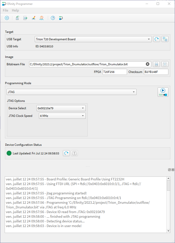
So the next step was to program the Sapphire RISC-V processor core provided by Efinix into the FPGA, in order to implement the whole file-reception program from the PC, as well as the routine to write that file to the Flash.
When I do feasibility tests, the code I write is never very clean. Rewriting it for the final implementation allows me to follow a cleaner structure.
To check that the application code for the processor was starting to work properly, I simply programmed the UART for communication with the PC, the processor's internal timer to generate a one-second interrupt, and the timer interrupt routine to send a CRC-16 character (actually the character 'C') to the PC. Indeed, it's upon receiving this character that the Ymodem transfer protocol can start transmitting.
Because, no, I'm not using the Windows copy-paste file system over USB media. That system isn't designed to be controlled — it either works or it doesn't, with no visibility. So I preferred a more controllable transfer method.
And that's when the real trouble began. Although the code running on the processor started correctly and displayed the program prompt along with a few occurrences of the CRC-16 character, the program would stop without any intervention from me.
For a main loop consisting of while(1); that's a problem.
So I spent an evening eliminating possible causes for this malfunction. Then I remembered a small electrical issue I'd encountered during my initial tests a few months ago — a minor problem with ground loops and/or noise. This issue was obviously causing disturbances on the JTAG link, which in turn would crash the processor.
I inserted a USB isolator dongle on the USB hub and plugged the JTAG dongle into it.

And this time, no more problems. The processor runs its program without any issue.
So, my very first 4-layer PCB I designed, even if it's not the pinnacle of the art in this field, isn't causing any issues so far. The code I developed on the Efinix evaluation board works as well. Up until now, the most complex systems I had produced were circuits around Gowin FPGAs, which are simpler to implement. For this MSX cartridge, the whole circuit is nevertheless a bit more complex.
I must say I'm quite pleased with the result :