mercredi 6 octobre 2021

The Wichit Sirichote Z80 MICROPROCESSOR KIT and the µPF--2

After thinking about what could become of my improved version of the Z80 µPF - 1 compatible kit from Wichit Sirichote, I thought that the first thing to do was to take full advantage of the Z80 hardware emulation in the FPGA.

In fact, the Z80 encoded inside the FPGA can operate at the native frequency of the QMTECH board, which is 50MHz. It would be possible I think to go up to 100MHz using a PLL but in the context of a learning board, I did not consider it necessary to exceed 50MHz.

Obviously, it is not enough to change the frequency of the processor to make the system working correctly. Indeed, apart from the internal resources of the FPGA, the external resources operate at much lower frequencies. This is the case off the I2C bus, the LCD display etc etc ...

By properly managing the internal processor frequencie, I have succeeded in achieving a fully functional system. 

So all RAM ROM access and internal FPGA peripherals are now running at 50MHz. This represents a speed approximately 14 times greater than the original 3.579MHz of the Wichit Sirichote Z80 kit. 

This can make it possible to consider applications a little more 'serious' now!

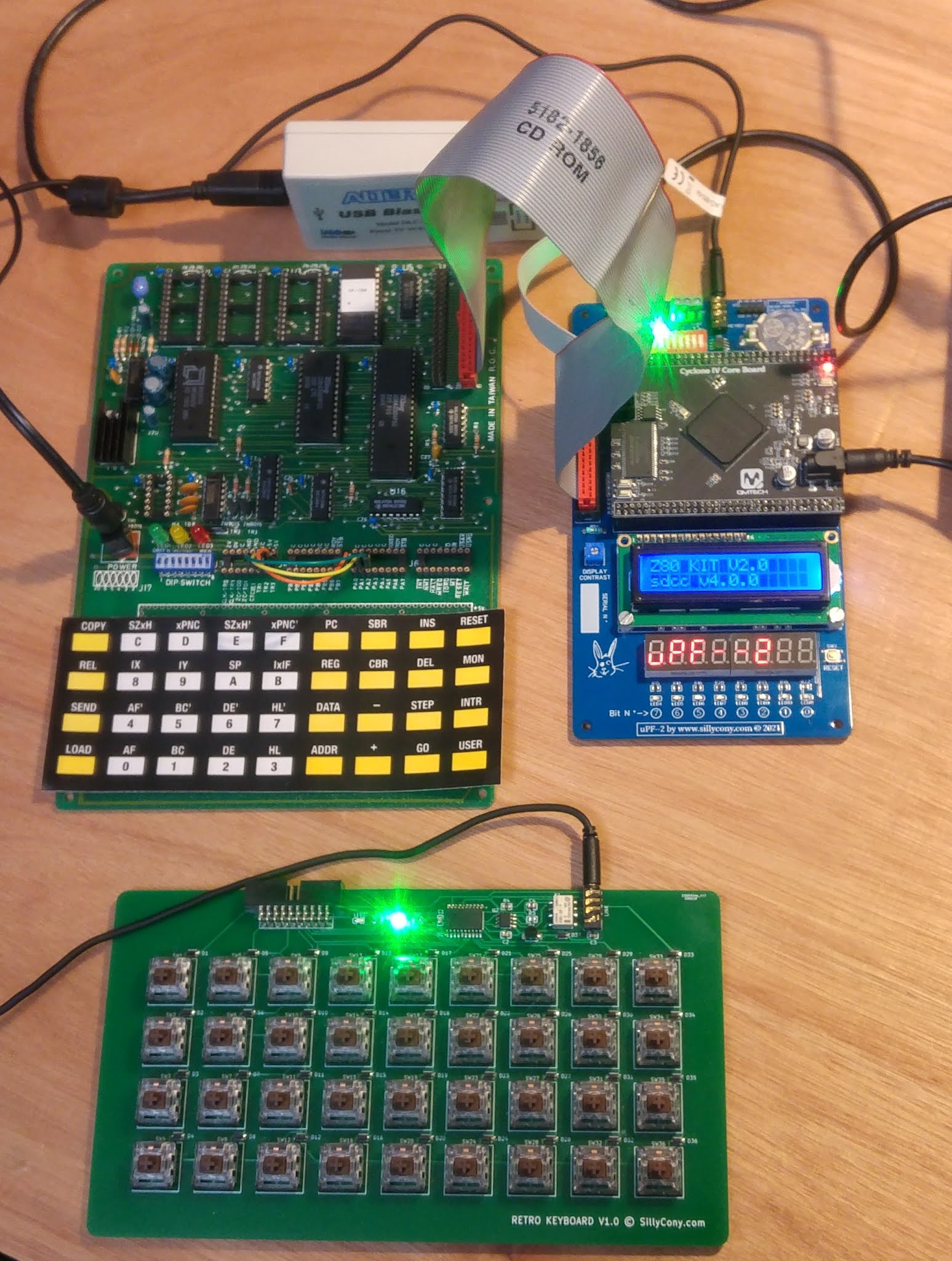
Wichit Sirichote µPF--1@3.579MHz VS µPF--2 @ 50MHz

As can be seen in the image above, the µPF - 2 kit has a separate mechanical keyboard which is very pleasant to use, unlike the keys used on the original kit.

Communication with a PC is now carried out at 38400 baud and no longer 1200 baud. Or a file download speed multiplied by 32!

Obviously, now the file download is proceeding correctly. There is no more corrupted informations. This is mainly due to the fact that I used a real UART and not a slow emulation performed by the Z80, like on the original kit.

The majority of the code now runs at a speed of 50MHz and no longer at around 3.5MHz.

The µPF - 2 kit also offers other resources such as the native LCD display as well as a real-time management circuit.

Z80 @ 50MHz!

To make this all possible, I also rewrote a lot of the code of the monitor. I haven't completely finished this job yet. I also still have a few details to finalize on the VHDL code for the hardware emulation. I expect to carry out these operations in the next few days.

So, I now hear in France, that it is becoming difficult to find people with basic skills in digital electronics and that the National Education no longer trains this type of person.

This is true, and false. False, because a few excellent branches still exist, but very few highly qualified personnel are trained. True because there is no longer any training allowing a larger number of talented people to be trained in this type of technology.

This is nothing new. Reason why I personally learned digital electronics and more particularly processor systems on this type of material, in the 80s.

We may not realize it, but even today, a very large number of applications are built around the Z80 or other processor like the 6502. Modern technology makes it possible to use this processor in an FPGA and thus to obtain inexpensive but nevertheless very powerful hardware. And imagine that it is possible to implement an FPGA with 8 or 16 Z80 cores at 50MHz or 100MHz without problem. What flexibility!

mardi 21 septembre 2021

Retro computer : RETRO II, a clone of the APPLE IIe computer.

Among other subjects, I have been assembling for a few weeks an APPLE 2e compatible board, The RETRO II.


I did manage to get the system start page but it wasn't easy. 


More details here: https://sillycony.blogspot.com.


mercredi 15 septembre 2021

Audio Direct Box prototype.

EasyEda is really an interesting PCB creation tool. I often use it for fairly simple circuits, and it does its job very well. I am currently working on the prototype of one board of my futur multi direct box :


Selection of one of the three unbalanced sources and electrical isolation and symmetrization of the output signal. 

Obviously, it's a little more complicated than performing this function with an audio transformer. And then I would probably have some modifications to make to the schematic based on the measurement results of this prototype...


mardi 7 septembre 2021

FNIRSI-1014D and audio direct box.

Back to business after a few weeks of vacation. After a lot of buzz about FNIRSI's entry-level oscilloscope, the Model 1014D, I ended up buying a copy. 


The main reason is that on the one hand I did not notice too negative comments on this device, but above all three essential points: speed; clarity of the screen; silence.

I specify that I am absolutely not sponsored by FNIRSI.

In addition, I am currently looking for an audio mixer to mix the few electronic devices I own. Because I do not have a lot of space, I am forced to choose a rack version. So I have two models in view, the Yamaha TF-Rack, and the Behringer X32 rack.

Yamah TF-rack

Behringer X32-rack

In fact, for reasons of lack of flexibility in auxiliary inputs / outputs and overall the closed aspect of the Yamaha console, I rather want to try the Behringer model. In addition, while the audio qualities of the Behringer console are known to be very good, it costs however half the price of the Yamaha console.

But, of course, the input type of these two consoles is quite different. The inputs of the Behringer are symmetrical. Yamaha has therefore chosen to place unbalanced inputs directly compatible with synthesizers. This would have the immediate effect of choosing this type of console for a studio, rather than the Behringer console. 

Because in fact with the Behringer mixer it is necessary to convert the unbalanced output of synthesizers to the balanced inputs of the Behringer mixer. And that at a cost, typically between $ 100 and $ 120 per conversion box.

Also consider the fact that even in the studio, the multiplicity of materials inevitably generates a 'ground loops', generating noise and hum.

The price of 16 'direct box' being nevertheless rather high cost, I decided to develop a solution allowing to regroup in a single rack all the desired functions.

I therefore plan to build a rack allowing the selection of three line-level inputs per audio channel. Each audio channel will be isolated from the ground of the rack, and therefore from the ground of the console. Finally each Audio channel will provide a balanced output for a direct connection to the Behringer console. Each Rack will provide 8 audio channels to the console while having the possibility of selecting three sources per channel.

It is possible to use audio transformers specially made for this function in order to ensure the electrical isolation between the audio input and the audio output. But the price per unit of these transformers is too high for this type of realization. to be connected to a console of about $ 900.

https://www.audiophonics.fr

Only the active solution remains with the help of electronic circuits. The degradation of the signal will therefore be greater than the transformer solution, but the use of quality components should allow the transfer of a quality signal. 

So I carried out a preliminary test on a breadboard :

And the results obtained with the 1014D oscilloscope :


The yellow signal is the signal generated by the oscilloscope's internal generator.
The blue signal is the signal obtained after passing through the electrical insulation stage. 

At 20KHz, the signal is very correct and remains very good  on the lower frequencies. The square signal is a little worse, but it is difficult to get a real idea of ​​this type of signal with a flying wire assembly.
I'm waiting to have made a first prototype to get a real idea of ​​the performance of the circuit.


And now, the two signals in phase opposition after simetrization. Here too, the signals obtained are good, with one of the two with the slightly greater amplitude. The capacitors and resistors used are not very precise, which can explain this phenomenon.

Conclusion: in fact, the system works very well. The results are in line with expectations. I did not estimate the cost of this realization, but the NE5534s used are not very expensive and not the ssm2142 either.

Conclusion on the use of FNIRSI 1014D: First of all, it is not a professional device. But this, everyone knows. The biggest concern is the signal reference error. The zero volt on the display does not correspond to the reality. There is a 1V to 2V offset on each channel. Sometimes the trigger level control becomes unresponsive. The operation of automatic measurements works but most of the time, adaptation is not made to the display. Signals are out of frame. And a few other minor annoyances.

But this is compensated by the very fast operation of this oscilloscope. Even if you decide to turn it off and on again, the operation only takes a few seconds. The commands respond very well which allows a 'reflex' use of this device. Therefore, It is never boring to use. Transferring screenshots is extremely easy and efficient. The screen is really very pleasant to look at, even at an angle. 

And above all, it's small, light AND quiet! This last aspect allows me to spend hours on a montage without having that very distracting fan noise present in most oscilloscopes. Suddenly, I can allow myself to think quietly about the modifications to be made to the assembly while looking at the result on the oscilloscope, without having to turn it off between each measurement session. It's a real pleasure.

For around $ 160, this oscilloscope allows real experiments, without too many worries, even if you have to pay attention to the ground of the two channels. This oscilloscope is not made to take measurements in the field, nor in a hazardous electrical environment, nor to make precise measurements. But it is perfectly suitable for testing analog or digital assemblies up to a few tens of MHz and under a few tens of Volts (40V max). 

The logical procedure, with this type of oscillosope is quite simply to use another more professional machine to validate the circuit once the prototype has been made. So, I am not at all disappointed with this 1014D. For the moment there does not seem to be an update on the manufacturer's site. I will look from time to time to check if small issues are fixed by future updates.


mercredi 14 juillet 2021

Thoughts on the µPF--2 Z80 kit dev board.


In fact, when I look at the system I built, even though I did it based on compatibility with the original µPF--1 kit at the time, I realize that my version looks more like a microcomputer than a development board.

https://collection.onceuponabyte.org/ident/COMP-0156


At the time, when I studied with this machine, in 1987 I think, the PC was not yet very widespread. There was no adequate development software and furthermore the µPF - 1 did not even allow program loading through a communication port.

It was therefore necessary to provide all the hardware and software functions to allow the entry of mnemonics in assemblers, live editing and correction, memory modification, program launch etc etc ...

As my kit works, in fact I realize that I am exclusively using the C language, a PC text editor, and the SDCC compiler. Then, once the program is completed, I download it directly into the µPF - 2 and start the execution. I absolutely do not use the basic functions of the system.

So I made the decision to convert this set into a modern Arduino style development system but still keep the 'retro' side thanks to the Z80 hardware emulation. The entire development process will take place through the serial port via the standard tools available for PC.

The objective is to be able to train easily and in a fun way, not only in programming, but also in interaction with the outside world and finally that real applications can be managed by this system.

Multitech IOM board

I am therefore going to develop a first interface board like the IOM original board which will allow the µPF - 2 to be autonomous, capable of loading its application program itself, launching it and of interacting with the outside world in the manner of an automat. 

Do not hesitate to send me your comments.

Best to you.


dimanche 4 juillet 2021

Back to the 90s


At the time, I saw this kind of covers on certain magazines. There was something other than the extreme and boring standardization of Apple and Microsoft. 30 years of crossing the desert! A new start, I hope, for other things more eclectic and more interesting...

vendredi 2 juillet 2021

A SMALL MIDI TOOL (next)

Another problem that really annoys me when I want to quickly jump to a patch on a specific synth. is that it is never easy. You have to go to the PC to play with the mouse, or type on the series of control keys of a particular hardware sequencer. Or more simply, get up from your seat to change the patch directly on the machine.

I decided to create a small simple module allowing to select a MIDI channel as well as a change of patch on the selected channel.

Here is the result of my thoughts on the subject:


Unlike the Midi Merge Box project, here, the system must fit into the MIDI chain. The system cannot therefore be passive and must insert the patch change commands only when the MIDI 'network' is available.

The second challenge consists in power the Patch selector from the MIDI bus. Indeed, such a device which must be inserted in a MIDI chain can be very quickly painful to use if in addition it is necessary to manage the power supply unit.

To do that, it is necessary to develop a system whose power consumption remains below 20mA, ideally below 15mA. this time, I chose a microcontroller that I haven't used for over 15 years but which turns out to be very energy efficient and above all very easy to program / debug.

At the stage where I am developing my little studio, I have now to decide for a mixing console. I would go for a RACK version because I don't have a lot of room in my studio!

What do you think of Yamaha's TF-R rack console?


Tell me if you have any comments on this console ...