vendredi 8 avril 2022

Drumulator in FPGA & MSX news &...

It's been a few weeks since I posted anything. However, I worked on four simultaneous subjects.

  • Troubleshooting the CSQ600.
  • The development of the MIDI switch.
  • The finalization of the USB keyboard converter for Omega.
  • The test of the audio output of my future Drumulator. 

CSQ-600: 


Unfortunately, I couldn't get the machine to work. However, I installed a new processor, but the result is strictly identical to that of the original processor. I just managed to have a different start of the machine by replacing the original oscillator with a signal generator. The result is insufficient for me to get an idea of ​​the problem for now. After a few days of intense investigation, I momentarily put the subject on hold.


MIDI SWITCH :


I made some progress on the subject. I mounted a module with four RJ45 inputs/outputs as well as a small conversion 'pod' to MIDI IN/OUT. I'm currently stuck because I can't get my hands on the small processor used on the PODs. Fortunately, I recently found availability for this processor and ordered a few copies. I am awaiting delivery.

USB KEYBOARD CONVERTER :


I am pleased to announce that the development of this interface is finished. I finalized the code for 'AZERTY' and 'QWERTY' type keyboards. As a reminder, this converter allows you to connect a standard USB keyboard to the MSX OMEGA microcomputer. Also, I'm waiting for some components to manufacture a few copies that I will make available for sale for those who wish to go through this solution rather than building the OMEGA keyboard entirely.

The Omega computer

AUDIO OUTPUT FOR MY FPGA DRUMULATOR :


I completely coded the processor part as well as the waveform sequencer in VHDL. The goal is to fit as many logic elements of a Drumulator as possible within an FPGA. So I still had to study the audio output. 

The problem is of course, that the kind of digital to analog converter used in the Drumulator is absolutely no longer available. The solution adopted therefore consisted in using an available 12-bit converter, and in coding the system making it possible to reproduce the logarithmic transfer function of the original converter.

For this, I started to mount a copy of my analog output prototype:

Quick & dirty test plateform but sound very good!

To do my tests, I used a development board from STmicro equipped with a fairly powerful STM32 processor. This kind of board associated with the ST development software is really ideal. Once the system was set up, I encoded a square signal at 1KHz using Audacity which I exported in µ-LAW format to the development board. The result gives what was expected:


For this kind of test, low precision required and low frequency, the (toy) FNIRSI-1014D is ideal because it does not generate any fan noise. This allows you to leave it on for hours without wanting to throw it out the window at the end of the day ;-).

Finally, I replaced the sinusoid definition file with the one from the copy of the original Drumulator ROM to see the scrolling of all the sounds of the machine, given that I scan the whole 64K of ROM.

In fact I obtained the same result as that obtained by testing the waveform sequencer implemented within an FPGA, by directly sending the addresses to the ROMs present on the motherboard of the Drumulator test:


Basically, I have 'proof' of all the important parts of the Drumulator working. It only remains for me to test the analog output filters, knowing that there are recent components to replace the old SSM present in this section of the Drumulator. Each part works 'in its own corner'. Now it's all about putting it all together on a large prototype board.

I left my job with the madmen of the French national education since a few weeks, and life is much more pleasant now. I develop what I like, at my speed... Peace for ALL!


jeudi 17 mars 2022

Components shortage!

This story is starting to get a little annoying. In recent months, the price of components, particularly on silicon chips, had seen their prices explode. It is now becoming impossible to obtain them, particularly processors.

As a result, it becomes more and more difficult to advance in my developments. No more FPGAs, no more ARM-like ST processors: hum!!!!

Just to think of something else, I pulled out of the boxes a Roland CSQ-600 sequencer in poor condition and non-functional.

https://fr.audiofanzine.com

This is not my personal CSQ-600. The case is so deteriorated by rust that I do not prefer to display images that may offend the sensitivity of some ;-)

I prefer to display here, a picture of the cleaned motherboard of the machine:


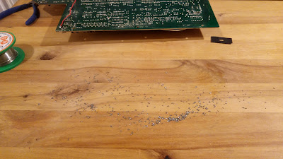
I did two main jobs on this board. The goal being to clean it on both sides, I started by cutting all the legs of the components. They were really too long and were going to bother me to pass the brush. Knowing that it was also possible that some bent legs end up touching and creating problems. Might as well avoid all these inconveniences.


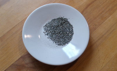
In the end, I ended up sucking all this little pile of bits of metal:


It took me some time but allowed me afterwards to properly clean the whole circuit board.

And, obviously, I had to redo some tracks located under the location of the original battery which, having leaked, had corroded and cut the 4 'usual' tracks.


After general inspection of the board and some soldering redone, I was able to power up the system.

And what happened?

Absolutely nothing!
flat cephalogram!


After having tested all the pins of the 8048 micro-controller, it turned out that absolutely nothing is happening on its input/output ports.

In fact, this is what I found:
  • On pins 2 and 3 I observe the system clock which is approximately at 5MHz.
  • The ALE signal is active.
  • Pin 16 (DB4) is stuck to +VCC and does not move.
And that's all! There are days like that.....................

For me the conclusion is quite simple: the processor is dead!

I don't know what happened on this machine. I bought it in the state and potentially not functional a few years ago for a few tens of Euros. It may be that there were tests performed in the wrong way, that the 5V was higher, and in this case other logic circuits will be destroyed etc etc...

At the moment, none of the circuits are getting hot, so I'm hopeful that all the logic on this board hasn't been destroyed. I always ask myself the question of what can destroy a processor. I have never seen a CPU die on its own. Most of the time it is a question of a bad handling which leads to the destruction of the circuit.

The problem is, first, I don't have an 8048 processor, nor the way to program one. I don't have the firmware dump either. Anyway, I found a supplier able to get me a programmed 8048. First of all, I will direct myself towards the replacement of this component.

mercredi 9 mars 2022

The great era!

And now :

In fact, telephone numbers in France went to 8 digits on October 25, 1985. The Drumulator was marketed in 1983. The copy I'm troubleshooting therefore went to Music-Lab between 1983 and the end of 1985. Almost 40 years ago... 


lundi 28 février 2022

What... A ZX81?

Yes, well, at some point of your life, we have to close certain projects that have been in progress for... a very long time, such as having a ZX81 at home.


vendredi 18 février 2022

DRMULATOR : The circuit board is finally routed!

Given the relatively small size of the circuit, I thought it was going to be complicated to route all the tracks. Ultimately that was not the case.

Everything is not routed according to the rules of the art. That's not bad, it will allow me to put my finger on the potential problems more easily.


We just have to wait for the receipt of the printed circuit...


mercredi 16 février 2022

Drumulator : about sound generation.

Now that I know how to manage the samples using the micro-sequencer I created in VHDL, I have to study the analog part using a converter other than the original one.

The AM6072 circuit is obviously no longer available. It is therefore necessary to use a standard DAC instead of the original companding DAC. I will use a lookup table in the FPGA to modify the response of the new DAC.

In order not to launch myself right now in the realization of the Drumulator clone, I must test the sound generation of the eight channels using the new DAC. So I started to create a little test circuit board:


I tried to keep the size as small as possible. You never know, if this board works well, I could use it as it is. However the implementation of the components is rather dense. I don't know if I will be able to route all the tracks correctly. 

To be continued...

lundi 14 février 2022

DRUMULATOR & FPGA

Some time ago, I coded the whole processor part of the Drumulator in an FPGA. I still had to code the sound generation sequencer. I thought it was complicated to achieve, given the schematic in the service manual.

The sequencer looks like this:


This sequencer controls a set of registers that are used to generate addresses for sample ROMs.


I was not sure how to go about writing readable and simple code from these two diagrams. After having understood the general operation of this system, I finally decided to transcribe in VHDL what I had understood. Good idea since these two diagrams are coded in about fifteen short lines of code.

To carry out the tests, I contented myself with using an FPGA board whose two buttons I use to simulate two Drumulator sound buttons. The FPGA then generates addresses for the Drumlator board ROM address bus. It's as simple as that and it works great.


The adventure goes on...