mardi 14 décembre 2021

A MIDI patch bay?

I have been looking for a MIDI bay patch for years, even decades. I even studied the feasibility of such a device on several occasions. In fact, the constraints in terms of feasibility, complexity, functionality and price are really strong. 

On the strength of all my tests, I decided to tackle the task again. I am currently studying the motherboard of such a device:


This is only a first prototype but the final version should look very much like this, in much smaller ...

vendredi 10 décembre 2021

DRUMULATOR repair man...

December 10, 2021 : 

The Drumulator that I received a few days ago and spent an hour or two on doing dreadful 'hacks' done by bad tinkerers and replacing a few circuit sockets reboots : 

This is obviously not very visible in the photo, but the superb and heartwarming message "bad" is displayed. I haven't tested the sound generation system, but anyway, I have to use this board to test this generator from an FPGA implementation.

So far I have only changed the CTC and a 74LS145. By the way, it is getting quite difficult to find this 74LS145 nowadays. I bought ten. We never know ;-)

UP December 14, 2021 : 

As often on Drumulators, the RESET circuit no longer works and the SRAM is no longer correctly saved. However, I did manage to RESET the machine and program sounds to each PAD. It works. So I know that the sound generator is also working, as well as the whole audio processing chain. I will definitely be able to use this machine to test my sound generator implementation! 

On the other hand I have to clean all the switches because they do not respond well. One of the pads has been damaged. I don't think I will be able to get it to work normally again. Ah, what all those Sunday DIYers are !!!

UP December 16, 2021 : 

As I now know this Drumulator is functional, I can prepare it for my micro waveform sequencer tests. 

So I removed the two circuits which buffer the addresses generated for the sound ROMs. It is on these two new circuit supports that the address wires generated by my FPGA emulation will take place.


The most difficult being to remove these two circuits without damaging the PCB, nor the circuits because they are not very easy to find nowadays.


jeudi 9 décembre 2021

RETRO COMPUTING : TMS1122NL

There are a lot of digital clocks.
Those made in China which are inexpensive and incapable of any precision.
There are those, a little more serious and more expensive, which are precise but have 2 buttons for 20 functions.
There are also those which are beautiful, with nixie tubes for example, but which are really too expensive.
And then, none is capable of controlling the start or stop of any device.

In 1981, I came across an article in the French review 'Electronique Pratique' about the making of a clock with very interesting characteristics.

Magazine cover.

The circuit used was a 4-bit microcontroller of the TMS1000 family, which appeared in 1974. The TMS1121 / 1122 was a version containing a programmable clock application directly programmed into the internal 1024-byte ROM. 

The result was an extremely practical and easy to use device. I have never found such pleasure in using a simple clock. Unfortunately, I did not keep the copy I made in 1982, thinking that this machine was obsolete and easily replaced by a more ergonomic device: big mistake!


So after a number of years I decided to recreate a equivalent circuit to the TMS1122. Although the original clock was absolutely 'great' for the time, it suffered from two issues. The accuracy of the time was linked to the accuracy of the 50 / 60HZ network. In addition, it did not display the seconds and did not manage them in programming, which could be handicaping for certain uses.

The diagram for using the TMS1122 is very simple :


In my new version, there will be just a few additional displays and the time will be taken directly from a specific and very precise component. The operation will be the same except that the seconds will also be managed. In addition, in order to eventually be able to control this clock remotely, the circuit will be equipped with a serial port which will accept exactly the same commands as those typed on the keyboard.

Note that in the past, some people have developed real replacements for TMS1121 here based on a PIC ic :

http://xyama.sakura.ne.jp/hp/TMS1121_Simulator.html


mercredi 8 décembre 2021

New DRUMULATOR at the workshop & FNIRSI 1014D

A few days ago, I posted here a search request of a living or dead Drumulator.

I just received a machine that no longer works. It seems normal to me given all the tinkering she has undergone. After some investigations and component changes, I was able to see that the processor is working properly.


In red, the IC sockets that I changed, in yellow, the changed components, the CTC and a decoding circuit for the display (for the moment I have not changed the decoding circuit because I have to find a 74LS145 that I don't own).

At the moment I do not know if other circuits are defective. I don't know if everything related to the sound generation works but it is not very important. I just want to use this Drumulator board to test my digital FPGA implementation of this sound generator. I just need the D / A conversion and audio output part.

I have said it before, and although not sponsored by FNIRSI, it is a real pleasure to work with the 1014D oscilloscope. The screen is super nice, for frequencies of a few MHz it is fast enough and above all, it does not make any noise and is super light to move on the workbench. It is really very practical for this kind of little troubleshooting.


mardi 30 novembre 2021

MSX, CANIVORE & various thoughts on the MSX standard and amateur work

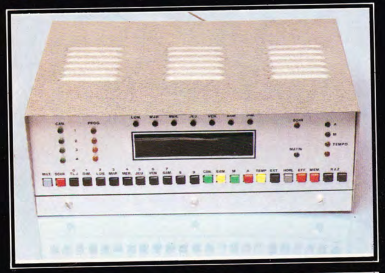
Several months ago, I started building an MSX compatible computer board. This is Sergey Kiselev's OMEGA project


I have no complaints about this project. Apart from the difficulty of supplying certain components and possible assembly errors, the computer works as soon as it is switched on.

I have already had the opportunity to discuss the cost of producing such a project. This is why I did not realized the keyboard proposed in this project, but rather a USB adapter allowing the use of a standard keyboard at low cost.


In order to put this computer into real operation, I therefore obtained a CARNIVORE 2 cartridge which provides, among other things, access to a storage medium in the form of a FLASH card:


And now is the time for things to get complicated!

At first, I tried to run the cartridge with a flash card that I had. Despite my best efforts, and although the cartridge menus were displayed, the flash card was never taken into account. So I ended up looking for a possible compatibility problem with my flash card. The flash card that I have and that works on my PC :


You can find a list of compatible flash cards here: https://sysadminmosaic.ru/en/msx/carnivore2/qvl_list. I was indeed able to find this type of card in the list:


So I began to suspect the operation of the CARNIVORE cartridge. The first approach is to redo the welds. In order not to damage anything, I therefore used a hot air iron. I am used to work with this type of material so no problem. The result was the inability to start the cartridge itself.

So this time I visually inspected the cartridge and this is what I discovered:


From what I have been able to observe, it seems obvious to me that under these conditions the access to the memories of the cartridge, and therefore to the program in ROM seems highly compromised. 

This is the original placement of the component. I absolutely did not touch the legs of the FPGA. The fact that the cartridge started when I got it seems have been a miracle. In the current situation, it is not possible to properly realign the pins of the FPGA. The only solution would be to remove this component and replace it with an FPGA with the pins correctly aligned. This problem only exists on one of the four sides of the component.

Well, the Cyclone II series FPGAs are no longer manufactured. And moreover it seems very difficult today to obtain such circuits!

Which brings me, after having worked for several months on this MSX board, to the following thoughts:

  • Personal creations always come up against the problem of the case. Which one for OMEGA?
  • Two cartridge ports, at the time it was probably perfect, but today?
  • Operating mode selection by pressing specific keys at start-up: boring and outdated!
  • C-bios is not a system. It just offers the minimum API to run some cartridges.
  • Difficulty finding a version of the system corresponding to the needs.
  • Slowness of this type of machine. More efficient solutions are possible ...
  • Video resolution is really minimal ...
  • Lack of structured, up-to-date and relevant documentation...
  • Use of bad technical solutions for some realization. In the case of CARNIVORE, fpga, resistance adaptations to voltage differences etc...
  • Etc...

While this type of machine could, if updated, provide real pleasures of use and programming, it is clear that entering the MSX world from scratch is not a trivial task. And yet, this type of machine can provide real development potential but still requires a flattening of the concept I think.

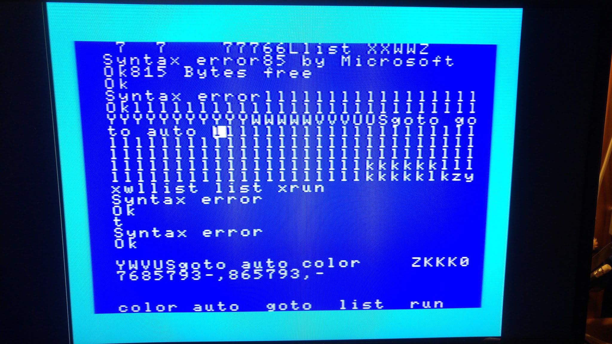
Don't make me say what I didn't say: making an OMEGA board and even starting it is a real pleasure. So far I haven't managed to start any application, and that's really annoying. 

But hey, that makes it possible to think of modifications allowing to improve the situation ...

vendredi 5 novembre 2021

Keyboard for OMEGA MSX Computer : it works!

It took me much less time than expected to be able to interact with the OMEGA board:

Before testing my USB to keyboard adapter board, I had tested the reception of codes from the USB keyboard. So I knew it was working. But I still didn't know how MSX BIOS scans the matrix keyboard.

After a few attempts and oscilloscope tests, I was able to send 'things' to OMEGA. But obviously not the right codes. After having researched the official codes of the MSX keyboards, I realized that the BIOS installed on OMEGA manages the Japanese keyboard! Why not!...

My first goal being to be able to type a little Basic program and run it, I decided to code the essential characters. First, the alphabet:


I am totally amazed at how easy it was to turn on my USB / OMEGA keyboard interface. I didn't have any issues with the design of the board, everything worked right from the start. Coding the software of the small STM32G0 processor was really very easy with the STmicro IDE.

For now, the coding is more of the quick and dirty type but it works very well!

On the way to my first "Hello World" program ;-)