mardi 10 décembre 2024

EMU 1 : Finally a first hope?

Since my last post, I have finalized the EMU1 motherboard DRAM test program.

The problem that arose when testing a 64KB bank and then the other 64KB bank was the management of the variables of my small application. Indeed, by switching banks, we completely lose the contents of variables, which can only crash the program.

How to do it then? One possible answer might be: no global variables to avoid fixed references, use the stack, and switch banks only from the main loop, never in a subroutine.

This way, you can use as many variables as you want, and the stack pointer is necessarily at its origin when you are at the highest point in the program: easy!

And that's how I was able to complete my program, and then test it with two DRAM circuits removed from the board.


I set up a small menu to launch the test, then to choose which bank to test. And on the terminal output, we can clearly see the two missing circuits, which therefore generate two errors.

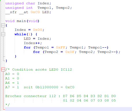
If we look at how the memory circuits are placed on the motherboard, we have this:


Which corresponds to the following logical organization:


I could have clearly indicated the address where the errors are found but converting from numbers to hex strings takes a lot of resources, in the little program space available, less than 1KB, it is impossible to implement. So, I simply indicate in which 16K segment the defective memory component is located.

If I take the example above, where the indication was RAS2/RAS6, knowing that I had previously selected bank no. 1, I know exactly where the faulty circuit is located.

And that in addition the crash occurs with the processing of 0xAA, I only have to target the four circuits corresponding to the '1' of 0xAA, that is: 0b10101010, or bits 1, 3, 5, 7.

Obviously, if there are more bits in error, this will involve testing all 8 circuits that make up the 16KB segment. But hey, it's already much more practical than just knowing that there is a problem on one of the banks...

So what, you ask? Apparently, I am now able to determine that there is no RAM problem, in fact. Because when I put the two circuits back in place, obviously, I no longer had any errors. Yes, except that...

That's when I decided to configure my program to test absolutely all memory addresses. To do this, I placed the memory stack at the minimum possible RAM space according to the number of bytes needed for my program. In fact, by successive tests, I placed the stack one byte above the value where the program crashes, at 0x040C. As a reminder, the first 0x0400 addresses are those of the ROM. The RAM therefore starts at 0x0400, and I placed the stack 12 bytes higher. Then, I configured the RAM scan to start just above the stack, at 0x040D.

And what do you think happened?


I have several bits in error on the RAS4 segment, since if you run the entire test, you see that I had first performed the test on bank 0 which had not generated any errors, then I selected bank n°1 to relaunch the test which generated these errors.

In fact, and as I was in the process of writing my program, I was able to test the RAM by starting the scan at different addresses. What I determined is that at 0x040E, I have the problem with 0x55 and that at 0x040F I have the problem with 0xAA. I am not able to know if it is the same component that is causing the problem. I am obliged to test the 8 circuits.

On the other hand, I don't know where the EMU program is stored, in bank 0 or 1. I also don't know how the two banks are used by EMU. At 27KHz, and given for 2 seconds of sampling, it seems obvious that only 64Ko are used for sound reproduction, and not 128K. In any case, if the EMU1 program is stored from the base of RAM in bank 1, then there is a guaranteed crash.

At least for the first time, I have a small lead to follow for the resolution of the machine startup problem. In addition, I am pretty sure that the CTC, the SIO and the PIO fulfill their function since to be able to communicate by serial link, I was forced to program these three circuits. And their operation corresponds to what was expected. I should also add that I also tested all the RAM circuits using a small DRAM tester of this type :


As for the EPROM programmer used in component test mode that did not detect a faulty 74ls00, would I be a victim of the same tool reliability problem? Hmm...

So....

vendredi 6 décembre 2024

EMU 1 : Finally a 'real' first program!

Of course, this may raise a smile, but it wasn't easy to get there!


This allowed me to verify that the serial interface was working in both directions, as well as that there were no errors on the first 64KB bank of RAM.

I still have to check the second bank. I don't know how to do it at the moment, since it will be necessary to do bank switching, otherwise my program will crash miserably.

mardi 3 décembre 2024

EMU 1 : Second attempt to write a program for the EMU1 motherboard

I think I finally found the problem of adapting the EPROM emulator. It must be said that it is not particularly easy to adapt an emulator that can only emulate at least a 2764 EPROM on a system designed for a 2708 EPROM!

This is not a problem with my EPROM adapter addressing, but with how the EPROM emulator works internally. For a 2764, it is absolutely necessary to send it 8KB of data otherwise, part of the code is simply not available at the output of the EPROM Emulator.


The usual little loop of sending strings through the serial port. This time the message is big enough to crash the system, but it seems to work.

It took several steps to be able to start working correctly with this EMU1 motherboard!

Well, tomorrow I'm programming the character reception in order to try to lay the foundations of a micro debugging system. I hope that what I've modified about the EPROM emulator will confirm the validity of my approach of today...

vendredi 29 novembre 2024

Manfred Veber, the guy who...

Have you seen the announcement on Facebook recently about the recreation of the specific buttons for drum machine like Drumulator, SP12, DMX, LinnDrum and others?

Hmm, and the one who did this is not unknown to me: Manfred Veber.


In fact I already had a contact with Manfred a few years ago by providing him with two copies of ELD5530, the replacement circuits I had created to replace the original CEM5530. Since then he opened his repair shop in Paris.

While passing through the capital of the kingdom of france, I took the opportunity to go and see him, in order to buy a few copies of these famous switches.

"I love smelling napalm in the morning." as he said. 

How to explain this? This smell of old electronics, very warm, which recalls the wonderful moments of my discovery of electronics at the end of the 70s, beginning of the 80s. Ah, what happiness : To each his own!


What beautiful machines!

My first real encounter with a DX1 or a Prophet 5. And there, there were some beautiful specimens of Prophet 5. A magnificent T8, Oberheims, Moogs and other beauties!


And meet her, also for real, with a passionate guy. An interview that was supposed to last an hour, like, finally lasted more than two and a half hours. We discussed technology, repairs and strange objects.


Have you ever seen these CEM5512 ?

Thanks to Manfred for this moment of sharing around these superb machines. And thanks for the twenty or so switches that I was able to buy.

The EMU 1 is taking up a lot of my time. It's bothering me a bit because I have the Drumulator subject to move forward: complicated :-(


EMU 1 : Second attempt to write a program for the EMU1 motherboard

After successfully getting the famous 'Hello World' of embedded computing to work, namely making an LED flash, I decided to tackle something bigger. 

The goal is to create a diagnostic program that can test the system operation. I don't really know how I'm going to do this yet because the EMU1's ROM space is only 1 KB.

But, what I know is that I want to use a method of communication with the diagnostic system, other than displaying error codes on the LEDs of the control panel. So the idea is to use the serial port of the machine to communicate with a computer, PC or MAC or Linux, through a terminal emulator.

And for the occasion, I decided to implement the use of the memory stack, thus allowing me to create functions with input parameters, even if sometimes the compiler used, SDCC, directly transmits the parameter via the processor registers.

The previous program to flash a LED was so simple that I directly programmed a 2732. But now, as I want to develop a much more complex application, I decided to use an EPROM emulator.


I have been using this emulator and it works very well for years. In order to be able to use it on the original 2708 socket of the EMU 1 motherboard, I had to mount a small adapter, since the emulator is only able to emulate EPROM components from the 2764.

In order to check the possibility of such operation, I loaded this EPROM emulator with the binary of the LED blinking.


This worked without any problems, ensuring that my binary file converter, as well as the operation of the board with the EPROM emulator, was validated.

Yes... but no, actually. It took me a while to get all the circuits programmed correctly to be able to send my first characters through the serial port.

At first I was using a RS232/USB serial adapter. Nothing happened. By doing some tests on the output buffer, I realized that the output was not following the input. Another malfunctioning circuit: a MC1488.

Later, I had quite a few difficulties to output characters through the SIO port B. The operation of the SIO requires, not only to configure it and also to configure the CTC, but also to configure the PIO. Always this usurpation of the DMA1 for the management of the floppy drive. If the PIO port B is not correctly programmed, the SIO will not output any characters.

I did of course eventually get there. So I have 9600 baud character transmission from the EMU 1 motherboard to my PC.

Yes... but not so well, actually. Because something strange is happening. My test program, which simply consists of emitting a string in a loop, crashes under certain conditions. What conditions?

And this is where it gets hellish, because nothing makes sense. Basically, I obviously suspected that my conversion routine had a coding problem, I suspected that there was a RAM memory problem that was causing problems where I had initialized the processor stack pointer etc etc... I couldn't get any conclusive results.

And then, at one point, I realized that the problem disappeared when I decreased the size of the string. This string is placed just after the main() routine and just before the functions by the SDCC compiler. The emission of a string is done using a function placed at the end of the program. The result is that when I decrease the size of the string, the overall size of the program decreases and the last instruction of the send function appears to fall back into what I assume is the safe domain of ROM memory space.

After some unsuccessful tests, I concluded something 'crazy': that the emulator must have a problem and, for a reason that I don't understand, not provide the right codes on a part of the ROM space.

I have two Momik emulators. I tried the second one, with the same result. Which made my perplexity even worse. The doubt becoming unbearable, I plugged the EPROM emulator into the EPROM programmer, in order to read its content. And there, the jackpot, a whole part of the code does not correspond to what I send to the EPROM Emulator.

Until now, I was doing my tests with the EPROM emulator connected to the memory adapter that I made. In order to be sure, I remove it from the emulator that I program this time to behave like a 27010 in order to position all the pins at a determined level, and I read this time the emulator by specifying to the EPROM programmer to also read a 27010. And there you have it: the reading is correct.

To confirm my result, I put the EPROM adapter back on the emulator and reread it. As expected, part of the code read is 'rotten'. So be it! I checked the modification I made on the EPROM adapter, everything seems correct to me, except that to go from a 2708 to a 2764, the minimum component that the EPROM emulator is capable of emulating, I have to use the /OE signal instead of the /CS signal, the /CS signal being directly connected to ground.


In fact, /CE, A10, A11 and A12 of the 2764 are connected to GND. /PGM, +12 and -5V having been directly connected on the motherboard when moving from the 2705 to the 2716.

With the adapter corresponding to these changes, the data is placed in the right place, but it no longer corresponds to anything from the second data block. This is not an addressing problem, otherwise the data blocks would not be placed in the right places.

So, after a long time of research, I finally understood that my program problem most likely comes from the EPROM adapter that I mounted. However, I do not understand the phenomenon at all. I still have some research to do at this level if I want to be able to fully use the EPROM emulator to develop my diagnostic program.

It's really not easy to 'play' with EMU's productions. These guys were really 'crazy' in electronics ;-)

mardi 19 novembre 2024

Drumulator and Efinix FPGA.

I'm busy trying to get the EMU1 working again, but I finally received the test control panel. I will finally be able to start testing the implementation of the CTC component inside the FPGA :


Obviously, the final panel won't look quite like this. It will also depend on the type of switchs that I can find for triggering the sounds.

Maybe a newly recreated switchs like these :


dimanche 17 novembre 2024

EMU 1 : First attempt to write a program for the EMU1 motherboard

As I indicated in my previous post, I now need to know if the DRAM on the EMU1 motherboard is fully functional or not.

As a reminder, when I had this EMU1, a few years ago, I was able to load a sound disk without the slightest problem. Then the machine smoked. Nothing serious, a few tantalum capacitors shorted. I replaced these capacitors and reassembled the machine without ever being able to restart it. Since then, it has never managed to read a diskette. So I had tested all the DRAM components with a small tester which had not indicated any faulty components.

Due to the multiplexing mechanism of the DRAM address bus, using 'criminal' timings performed with resistors/capacitors, I am therefore trying to get an idea of how this system currently works.

To do this, I will write a very simple program whose goal will be to represent on a series of LEDs connected to an output port of the EMU1 motherboard, the evolution of a simple 8-bit counter.


This program, of rare complexity, simply increments an Index whose value will be sent to the IO address space 0xC0 (__sfr __at 0xC0), in a loop slowed down by a timer consisting of two nested empty loops. There is no prior initialization of the Z80 registers. I do not use IRQs or the memory stack.

This simple program requires 5 bytes of RAM memory. If it works, it will already indicate that the DRAM components are being accessed 'relatively' correctly. If this program works, I will modify it to test the entire 128KB of RAM.

I compile this program using SDCC and the command:

sdcc -mz80 --no-std-crt0 --vc --code-loc 0x0000 --data-loc 0x400 TestRam.c

No special comments. The code starts at address 0x0000 and continues and uses only a few bytes of program area. The data in RAM will be positioned from address 0x0400, just at the beginning of the RAM space, just behind the first KB of code.

And now??? Well, we need to encode the content of the ROM code obtained after compilation and conversion into a binary file to make it compatible with the wiring system made by EMU (thanks EMU)!

Even for a few bytes of ROM, I preferred to write a small program under Windows to automate the task. Because it is necessary to encode not only the data but also the addresses. So as I plan to expand this small test program, I might as well make this encoding process as automatic as possible, even if it means 'taking' a little time to write the Windows application.

I hate using Microsoft's Visual C++. A gas factory, a big piece of crap (for me, because there are thousands of programmers who love Visual C++), GB of data to load and never knowing where we're going! So I tried it with QT. Its mode of operation is much more logical/simpler/efficient for me. Starting with no knowledge of QT, I 'only' needed a short day (I program embedded and am very bad with OS applications) of discovery to be able to write a minimal application that suits me.


So I know that the original EMU executable is 60 bytes. It's 'big' for such a small program, but I coded it in 'C' and not directly in assembler.

And for comparison, here is what the contents of the original binary file look like :


And now the binary encoded in the EMU 'way':


Well, if I understood correctly how the EMU1 motherboard works, if I also understood correctly the ROM coding system and if the DRAM multiplexing system is correct, it is not impossible that I can see something on the LED connector. Maybe not the progress of the counter if my temporisation is not sufficient, but still something...

Now I just have to program a 2732, put it on the motherboard, connect an LED and see if anything happens.

The result of my investigations in a future post...