lundi 7 février 2022

A MIDI patch bay : first start

About a month ago, I talked about the development of a MIDI switch based on an FPGA. This system will include logic elements, as well as a processor to control everything. There are proprietary systems for developing software for embedded processors quite easily. As I decided to use independent solutions, I had to implement mechanisms to allow easy debugging. In particular, I installed an external ROM support on which I can insert a simple EPROM emulator :


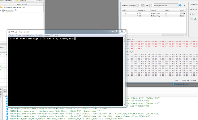
This makes it much easier to load a new firmware version. It is no longer necessary to go through the heavy tools of the FPGA programming software. At system startup, the RESET procedure copies the contents of the external ROM inside the FPGA. Once this is done, the embedded processor may start and display its prompt message:


There you go, the system is finally ready to move on to the application development stage. There is still a lot of work to do before a real test of the system, but it's progressing well!


jeudi 3 février 2022

I quit my job!!!


January 2022 was a bit special for me. I left my job as a computer scientist in the administrative services of a French university. After 20 years spent with fools, I decided that it was high time to resume the course of a healthy life, at least on the psychological level.

And it doesn't matter if it's me who's crazy!

vendredi 7 janvier 2022

A MIDI patch bay...

The Midi patch bay that I planned to create is quite complex. For this reason, I preferred to split the different parts on different PCBs.

About one month later...

First: the motherboard PCB which will contain the CSP (communication signal processor) as well as the USB interface:


In fact, all the data processing part will be integrated in a large FPGA in order to avoid the use of too many circuits.

mardi 14 décembre 2021

A MIDI patch bay?

I have been looking for a MIDI bay patch for years, even decades. I even studied the feasibility of such a device on several occasions. In fact, the constraints in terms of feasibility, complexity, functionality and price are really strong. 

On the strength of all my tests, I decided to tackle the task again. I am currently studying the motherboard of such a device:


This is only a first prototype but the final version should look very much like this, in much smaller ...

vendredi 10 décembre 2021

DRUMULATOR repair man...

December 10, 2021 : 

The Drumulator that I received a few days ago and spent an hour or two on doing dreadful 'hacks' done by bad tinkerers and replacing a few circuit sockets reboots : 

This is obviously not very visible in the photo, but the superb and heartwarming message "bad" is displayed. I haven't tested the sound generation system, but anyway, I have to use this board to test this generator from an FPGA implementation.

So far I have only changed the CTC and a 74LS145. By the way, it is getting quite difficult to find this 74LS145 nowadays. I bought ten. We never know ;-)

UP December 14, 2021 : 

As often on Drumulators, the RESET circuit no longer works and the SRAM is no longer correctly saved. However, I did manage to RESET the machine and program sounds to each PAD. It works. So I know that the sound generator is also working, as well as the whole audio processing chain. I will definitely be able to use this machine to test my sound generator implementation! 

On the other hand I have to clean all the switches because they do not respond well. One of the pads has been damaged. I don't think I will be able to get it to work normally again. Ah, what all those Sunday DIYers are !!!

UP December 16, 2021 : 

As I now know this Drumulator is functional, I can prepare it for my micro waveform sequencer tests. 

So I removed the two circuits which buffer the addresses generated for the sound ROMs. It is on these two new circuit supports that the address wires generated by my FPGA emulation will take place.


The most difficult being to remove these two circuits without damaging the PCB, nor the circuits because they are not very easy to find nowadays.


jeudi 9 décembre 2021

RETRO COMPUTING : TMS1122NL

There are a lot of digital clocks.
Those made in China which are inexpensive and incapable of any precision.
There are those, a little more serious and more expensive, which are precise but have 2 buttons for 20 functions.
There are also those which are beautiful, with nixie tubes for example, but which are really too expensive.
And then, none is capable of controlling the start or stop of any device.

In 1981, I came across an article in the French review 'Electronique Pratique' about the making of a clock with very interesting characteristics.

Magazine cover.

The circuit used was a 4-bit microcontroller of the TMS1000 family, which appeared in 1974. The TMS1121 / 1122 was a version containing a programmable clock application directly programmed into the internal 1024-byte ROM. 

The result was an extremely practical and easy to use device. I have never found such pleasure in using a simple clock. Unfortunately, I did not keep the copy I made in 1982, thinking that this machine was obsolete and easily replaced by a more ergonomic device: big mistake!


So after a number of years I decided to recreate a equivalent circuit to the TMS1122. Although the original clock was absolutely 'great' for the time, it suffered from two issues. The accuracy of the time was linked to the accuracy of the 50 / 60HZ network. In addition, it did not display the seconds and did not manage them in programming, which could be handicaping for certain uses.

The diagram for using the TMS1122 is very simple :


In my new version, there will be just a few additional displays and the time will be taken directly from a specific and very precise component. The operation will be the same except that the seconds will also be managed. In addition, in order to eventually be able to control this clock remotely, the circuit will be equipped with a serial port which will accept exactly the same commands as those typed on the keyboard.

Note that in the past, some people have developed real replacements for TMS1121 here based on a PIC ic :

http://xyama.sakura.ne.jp/hp/TMS1121_Simulator.html


mercredi 8 décembre 2021

New DRUMULATOR at the workshop & FNIRSI 1014D

A few days ago, I posted here a search request of a living or dead Drumulator.

I just received a machine that no longer works. It seems normal to me given all the tinkering she has undergone. After some investigations and component changes, I was able to see that the processor is working properly.


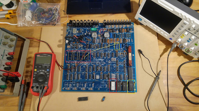
In red, the IC sockets that I changed, in yellow, the changed components, the CTC and a decoding circuit for the display (for the moment I have not changed the decoding circuit because I have to find a 74LS145 that I don't own).

At the moment I do not know if other circuits are defective. I don't know if everything related to the sound generation works but it is not very important. I just want to use this Drumulator board to test my digital FPGA implementation of this sound generator. I just need the D / A conversion and audio output part.

I have said it before, and although not sponsored by FNIRSI, it is a real pleasure to work with the 1014D oscilloscope. The screen is super nice, for frequencies of a few MHz it is fast enough and above all, it does not make any noise and is super light to move on the workbench. It is really very practical for this kind of little troubleshooting.