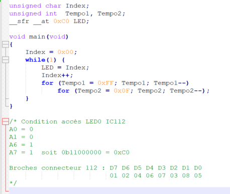
mardi 7 mai 2024

EASY USB, a MSX cartridge dream!

Since the beginning of the development of the MSX cartridge, I have integrated the possibility of restarting the MSX computer once the cartridge has been loaded via the USB port.

However, this requires making a small modification inside the computer. Nothing very dangerous since you have to connect a link coming from the cartridge to the RESET system of the computer. I personally installed a banana plug on the case of my MSX OMEGA into which I plug the reset signal coming from the cartridge.

However, not all MSX machine owners feel comfortable making this modification. The question that was then asked to me was whether it was possible to make an electrical outlet controlled directly by the cartridge. Yes of course.

To maximize safety of use, however, there was no question of directly connecting the cartridge to a switching system. I opted for a radio link with the use of small, low-cost modules, specially designed for this type of application.

Obviously, this requires manufacturing a small autonomous electronic system. So here is this system:


Quite simply!

I didn't make the 3D print of the little transformer that I ended up finding. 

But it gives an idea of what the final circuit will look like. A transformer transforms the mains current into 6Vac, rectified then filtered and regulated to 5V for the RF module and the two relay control transistors. Two transistor protection diodes are also installed.

Note that I inserted two relays for the two sector conductors. In this way, when the socket is placed in OFF, we will be sure that the devices connected to this socket will be completely removed from the electrical network.

lundi 6 mai 2024

A new Drumulator in the workshop.

This time, it is the machine of a French musical group which made itself known in the early 80s. History does not say whether or not this machine was part of the first successes of this group. Good question, by the way...

I have to admit that of all the Drumulators I have worked on, this one is in the best cosmetic condition. Almost perfect.

Let's go for the identity of the machine:


With the owner's tour of the exterior done, the big question: what about the interior? Because I was given to seeing dramatic things, of the true-false geek type who tried to add sound ROMs but who above all succeeded in crashing the machine by adding an incredible number of wires and modifications to the motherboard etc, which took me hours to remove!

In addition I have doubts about this Drumulator: result of tests or naval battle?


But no, there too, a nice surprise inside. No catastrophe in sight, at least other than a breakdown due to the machine itself and not as a result of outrageous tinkering.


We see very clearly that the machine has been updated with version 3 of the firmware for MIDI management. A MIDI input adapter card has been added as required, and placed/glued correctly. 

It is even possible to say that the original ROM was removed with a screwdriver since we can clearly see the surface condition of the first resistor above the ROM whose coating was burst with the place which served as a support for the screwdriver.

The battery has never been changed. Luckily, it didn't sink. I checked her, she's dead. As a result, sequence saving should no longer have been working for a long time. I imagine it is mainly used in MIDI.


You will have to remove it anyway and place a standard 20CR32 support somewhere on the case.

Little check, at least the voltage selector is correctly positioned on 230V:


Small observation, the motherboard also has an identification number. It is not the same as that of the machine :


The usual checks having been carried out, what is the problem with this machine? At first glance, it seems simple since the machine does not turn on at all.

Power problem or CPU boot problem? Again the first observations are simple, the motherboard does not have any DC voltage. Neither on the analog part, nor on the digital part.

We go back to the source: no sign of alternating voltage either at the two secondaries of the transformer. Hmm... We're getting closer!

The mains voltage nevertheless arrives at the primary of the transformer. No sign of heat or burnt, it does not seem that the machine was connected to 110V.

All that remains is to test the primary windings which are, at 230V, connected in series. The observation is clear, one of the two primaries is cut. The transformer is therefore inoperative.

This is very strange. Transformer connections appear good. No burnt rifle, no burnt marks, no hot smell. What could have been the cause of this breakdown? A manufacturing defect in the transformer?

Now knowing this machine quite well, to further investigate I will connect the digital part of this Drumulator directly to the 5V of a protected laboratory power supply. Even if the processor does not start, this will allow me to check the approximately real 'digital' consumption of the board.

A few days later:


After connecting a direct current power supply directly to the two terminals of the diode bridge of the 5V part: 1.2A at 6V at the output of the power supply, although programmed for 10V, and 0V at the output of the large 5V regulator placed on the 
metal part of the case:


Simple conclusion: regulator dead. I forgot to specify, but according to tests carried out on different Drumulators, in normal operation, that is to say with the displays on, the average consumption of the digital part of a Drumulator is around 1.2A. So, with the regulator in the regulation loop, I already have the 1.2A consumed and 0V in power on the logic circuits.

But at this stage, I still have to confirm that it is indeed the 5V regulator that is dead. So this time I connected the DC power supply set this time to 5V, directly in place of the Drumulator regulator output. To do this, I cut the three wires connecting the 5V regulator to the motherboard.

And this time, I have consumed 1.2A but with the logic circuits supplied at 5V. Confirmation therefore that the 5V regulator of the Drumulator is indeed dead. But, obviously, the machine does not start.

The design problem of this machine remains for me the detection of power supply operation. EMU has implemented a complex system to ensure that the machine's three power supplies are present in order to authorize the microprocessor to exit RESET. This doesn't do much except make testing the operation of the machine much more difficult. For example, it is impossible to test the digital part if the analog part is not powered. The best thing to do is to remove the power supply monitoring circuit and directly shunt the validation outputs to the desired potential.


All the transistors in this section are used to test the validity of the machine's three power supplies, and also to generate the processor RESET signal. RESET signal that this system generates poorly, which deteriorates over time, and which ends up no longer working at all. This is obviously also the case on this machine.

And I'm not talking about the different power supplies generated in all directions, which must be provided as best as possible during the test phase in order to put the digital part in 'potential' starting condition.

Brief! Having spent some time making the necessary modifications just to get this machine into potential boot condition, I ended up getting my favorite message on the displays:


At this point, I can only confirm that the 'computer' part of the machine is working. I don't know anything yet about the waveform sequencer part, nor about the analog output.

The only thing I can do right away is to change the faulty digit:


I seem to have one or two displays of this type in stock.

I will now pause troubleshooting this machine. To continue in better conditions, I need to redo the power supply, starting by finding a compatible transformer, i.e. with two output voltages available, as well as replacing the original 5V regulator with a switching model, more reliable and dissipating much less heat :


I have made this type of modification on several machines with very good operating results.


samedi 4 mai 2024

Retro computing : SGS Z80B & CDP1802D

Quite by chance, I went into one of the last electronics stores I knew to buy lead solder.

Yes, because when you do troubleshooting on old equipment, with nice ground planes, and more generally equipped with old-fashioned components, that is to say not CMS, well this 'green' solder which does not melt that from 400° and even on very small components, I have enough!

But that's not the point. While 'chatting' with the seller, I tell him about the end of production of the Z80. He tells me that he still has some in stock, but SGS. Hmm, I said to myself, not common indeed, especially new ones. And, as we were discussing on familiar ground, he admitted to me that he had something even more 'weird': CDP1802.

And there, in front of my amazed eyes :


A new CDP1802, in ceramic DIP: gorgeous!!!


A piece of computer history that I absolutely must revive ;-)

jeudi 2 mai 2024

Free advertising for FLIR

As you know, FLIR is a recognized manufacturer of thermal cameras.

Since I do electronic development, as well as electronic troubleshooting, this kind of camera is a very useful tool, sometimes allowing disaster to be avoided.

So, a few years ago, I bought a FLIR ONE:


Exactly this model and at this price, i.e. around €300 as of 02/05/2024.

This model, which connects to your phone, is much cheaper than a standalone camera, but still, it's not cheap.

I must have owned this device for 5 years now. All in all, I think it must have been used between 3 and 4 hours, about ten times 5 minutes per year. Because we must add that this camera, which has an on-board battery, has a ridiculously low autonomy. Less than 10 minutes when the battery is new.

And the surprise of the day: the camera no longer charges. suddenly,  it is in error and no longer work, even powered by their micro-USB port and connected to the phone: nothing!


This light remains desperately yellow, and the LED which normally lights green, on the other side of the camera, remains off, even after being 'charging' for 24 hours.

The verdict is clear: the battery is dead!

But the camera must be functional. So the annoying question: can we change the battery of this camera?

Well obviously not! No screws, everything is glued and cannot be dismantled without destroying the case.

The observation is also clear: Thermal camera very expensive in terms of usage time, little capacity in terms of operating time, and self-destructive.

However, I need this type of device. So yes, the camera is designed in America. But where is it made? In China, of course. Which allows FLIR to make a more than adequate margin, on the backs of the Chinese, and on that of my wallet.

$300??? The Chinese are now able to manufacture powerful phones, with crazy battery life, directly including infrared sensors for less than $500.

FLIR 'thought' of forcing me to return to them to 'renew' my infrared camera... Bad calculation. FLIR has definitely lost me!

vendredi 26 avril 2024

Ultimate MSX cartridge modification


I made two final changes to the design of this cartridge. 

First modification.

The first concerns the interfacing circuits with the MSX bus : Aoineko, the developer of the MSXgl graphics library who also tests the cartridge, reported to me problems with random startup of his computer. After studying his problem and especially after looking at the datasheet of his Panasonic FS-A computer, I realized that the power supply of this machine was 'unconventional' to say the least. This results in potential ground problems :


I guess you 'see' what I mean. The wire that serves as a ground reference is one of the two wires of an AC power supply! Hmm, I don't like that at all. 

With this type of design, the ground is always noisy for anyone who wants to connect to this type of device by taking the electrical reference of this ground. 

I therefore powered the cartridge interface circuits no longer directly with +3.3V via the cartridge's internal regulator, but directly via +5V from the MSX computer. No no, the problem was not a bad adaptation of the signal thresholds. TTL circuits work very well with commands not in +5V but in +3.3V. The HIGH level must be at least 2V, which is the case. On the other hand, it is true that this leaves a noise margin of 'only' 1.3V in the case of supplying the interface circuits with 3.3V, and given the design of the Panasonic FS-A1 power supply, I tell myself that that's a bit fair. 

Very good, but then I just postponed the problem elsewhere? It's true. But the interface circuits used, even if they can be powered by 5V, still accept signals coming from circuits powered by 3.3V. The minimum voltage for a high signal is 1.7V on these circuits. I therefore gain 300mV of noise margin. I hope this will be enough.

I still purchased a USB bus isolator in case my modification does not work on the Panasonic FS-A1. This will at least validate my 'theory'.


Second modification.

This time, it is the automatic RESET system of the MSX computer. I implemented directly on the cartridge, a system which allows the computer to be placed in RESET mode for the duration of the cartridge loading. In doing so, and once the cartridge has been loaded correctly, the MSX computer wakes up and boots directly from the cartridge : great!

The small 'problem' of this solution is that it is necessary to intervene inside the MSX computer to locate the reset system, in order to connect the RESET 'wire' coming from the cartridge. 

This is a very simple operation to carry out for those who know how to do it, but this is not the case for everyone. The solution then consists of finding a way to turn off the power to the MSX computer and then turn it back on once the cartridge has been loaded. Without using any wired connection because it is too dangerous. So I opted for a wireless solution.

I bought some small 433MHZ modules:


These models are simple enough to use and small enough to be integrated without major modification on my cartridge.


And there you have it... The first tests were functional. I was able to easily turn on and off a small LED connected to a receiver module placed a few meters away.

The receiver module:


To finalize the subject, all I have to do is develop the receiving system. It will simply appear in the form of a remote controllable mains socket. However, I use universal AC outlets so it can be used just about anywhere :


This circuit is simple and easy to assemble. I also think I will use it not only for the type of application targeted here, but more simply as a remote-controlled socket. You can easily find small remote control 'keys' on the Internet that will work very well with this HF receiver.

Warning :

The HF systems and the design of the cartridge have not been the subject of any certification request. However, the transmission power in games is so low that this does not pose a problem. However, not to be used in a sensitive environment such as healthcare centers....


samedi 20 avril 2024

A new era...

Zilog, after having been bought several times, and now owned by Little Fuse, has just announced the end of production of Z80 microprocessors.


The Z80 was introduced in 1976. I remember that year well.
I was 10 and it was the summer of the great drought in France. I discovered this processor a few years later, in 1982, when the ZX81 was available in classrooms. It was, and I only realized this a few decades later, too late for me,
but this is another story


The Z80 is the circuit that shaped my entire way of thinking about computing.
Even today, and even if I work with much more modern and faster circuits, it is my reference circuit. The very example of a computer resource accessible to all, democratic, lending itself to all eccentricities. Unlike the so-called IT of the following decades, which standardized the way of thinking, killed a certain vision of society, destroyed lives by its contribution to the creation of mass unemployment, and finally today, destroyer of human thought.

Reason for which I returned a little over two years ago to machines from the 80s, in this case the MSX standard.

The first MSX computer, th ML-8000 from Mitsubishi

Question: does this announcement of the end of availability of the Z80 signal the end of this craze for the MSX system?

No, obviously. And why? Well quite simply because there are implementations that are either more modern, like the eZ80, still at Zilog, or different, notably within FPGA. I myself had the opportunity to experiment with the implementation of Z80 within FPGA GoWin, during the recreation of the Micro Professor 1 computer. And it works very well.

SO? Well what I 'reproach' to the world of retro-computing is that it is too attached to the 'purism' of retro-computing. Obviously, this attitude can be greatly understood and justified. But, in my eyes, this 'prevents' any attempt to modernize the concept. It is also partly thanks to this that contemporary IT was able to be built, by the obsoletion of the existing, justifying this only by the financial aspect, and not by the real needs on the one hand, and on the other hand, the collaborative aspect of IT rather than the 'large replacement' aspect of a large part of the workers, thereby breaking the Fordian 'tacit contract'.

Today, there are many possibilities to improve the MSX concept, because it is an open system. So, the announced end of an era can, and will I am sure, allow the arrival of a new approach to retro-computing, which will certainly be 'neo-computing'. 

In any case, like the unexpected loss of the feeding bottle to the new born, thus forcing him to move on to childhood, the 'loss' of the Z80, will, I hope, encourage 'retro-computing' to move, therefore, to 'neo computing'.


lundi 15 avril 2024

8 Ports USB Midi interface.

This topic is a very long-standing one for me. I must have started thinking about it in the early 90s. At the time, the power of microcontrollers did not allow the development of complex systems. I then remember having developed a 68000 system to manage the 8 MIDI ports. I never created this system because I realized that it was far too complex to create and therefore necessarily too expensive.

10 years later, at the beginning of the 2000s, things improved in terms of the possibilities of embedded systems. So I tried to create this multi MIDI port using a micro-controller. I almost got there, but ran into a small problem, it was still difficult to find a circuit offering 8 serial ports and fast enough to manage them.

Everything changed in the early 2010s. At that time, it became possible to find a micro-controller circuit with 8 serial ports and enough power to manage everything. It was then that I looked into ARM type circuits from STmicro. From that point on, the problem shifted from the hardware to myself. In fact, in view of the possibilities of the new circuits, I wanted to add a whole bunch of functionalities, including USB bus management. Then, I entered into a spiral of redefining the functions of the object which, constantly, made me experiment with various solutions, all nevertheless unsatisfactory in my eyes. Unsatisfactory, because of the poorly defined hardware, and/or the software functionalities, which are also poorly chosen.

But, this series of failures allowed me to test a lot of solutions. And, a few days ago, as I was rearranging my stack of synths and rewiring everything, the obvious solution dawned on me. Now, right away, I saw very clearly what system I needed to have on hand to allow me to easily and flexibly wire all of my machines. I also realized that I wasn't far from the real subject, in fact. And that I just had to use all my previous developments and my previous ideas to achieve what I needed.

First, create not a hub or a switch, but simply an 8-port MIDI interface. I already have the prototype almost available. I just need to make some minor modifications to allow my 8 ports prototype to be connected to the USB port. So I have just made the necessary modifications to the circuit. 

The general idea is that it should remain simple to achieve. Thanks to the experience acquired with RISC-V processors during my previous work, I left with this type of processor :


It's a fact, the printed circuit board does not seem very complicated to make. Once the components are implemented, it should look like this:


As you might expect, the MIDI connectors are not shown in this 3D view. In fact, it is not standard MIDI connectors but RJ45 connectors that are used. This is a particular characteristic of my system.
 
The difficulty for me is not the creation of the card but its programming. Working with the USB bus is not always easy. Fortunately, a few years ago I implemented a 2-port MIDI interface on a USB port using an ARM microcontroller from STmicro. So I have a software base, I'm not starting from scratch. Even if this does not guarantee that I will reach the end, I also have no means of debugging the USB bus, I am relying on the experience acquired to complete this subject.
 

vendredi 12 avril 2024

A MSX flash cartridge downloadable from USB : the last iteration.


What is it about this time?


  • I did some redrawing work on certain tracks to make them more 'homogeneous'.

  • I powered certain interface circuits directly via the +5V power supply from the MSX connector and no longer with the 3.3V coming from the 5V USB to 3.3V régulator. the goal being to avoid electrical level problems with the test machine, a Panasonic FS-A1. In theory, 3.3V interfacing should not pose any problems, but in reality, it does.

  • And, I also added a small HF remote control module. This involves controlling remotely and without a physical link, an electrical outlet to automatically restart the MSX computer without having to manipulate the main switch, nor having to 'fiddle' with a RESET connection inside the computer. MSX. 


The final circuit should look like this :


Apart from the location of the HF module, the circuit looks almost the same as the previous version. Having written this, I also adjusted the external dimensions of the card so that insertion into the MSX connector no longer presents any potential gaps.

The final appearance should look very similar to this:


As for the code, the two programs concerning the processor which takes care of the USB communication and the one which manages the MSX bus, should not be modified. From the tests done, loading and making the loaded ROM available for the MSX computer works fine now.

mardi 26 mars 2024

A MSX flash cartridge downloadable from USB.


We have to be honest, developing quality equipment is not easy. Downloading a cartridge directly via the USB port from your PC to the MSX computer without any manipulation to do is a good idea.

But we must recognize that it is not done like that! I had to overcome hardware problems, software problems, implementation and component supply problems, etc. etc. 

Fortunately, most difficulties come from not having in-depth knowledge of the issues encountered. This is the study side of 'study and development'. We're getting there but it takes time.

So, after a certain number of prototypes, more and more functional, I am now arriving at the 'final touches'.

What is it about? In fact, with the idea of ​​making the loading and restarting process of the MSX computer automatic, just after copying/pasting a ROM file, you have to... restart the computer.

In 'real' life, a computer requires a power off/on sequence to restart on a new cartridge. This is not very practical. So I had the idea of ​​equipping my cartridge with a RESET signal output for the MSX computer.

Subsequently, it did not pose a problem for me to locate the right place on the OMEGA board to force the reset of the MSX computer.

But... that's not the case for everyone. And truth be told, I don't know many people who want to open up their MSX computer to solder somewhere a 'wire' from the outside.

In fact, you have to 'simulate' the action of the ON/OFF button on the computer. Again, there is no question of 'fiddling' with the computer switch. A relatively simple solution therefore consists of making a remote controllable electrical outlet. Obviously, there can be no question of connecting the MSX cartridge to an electrical outlet in any way.

A possible and elegant solution to this problem is to use an HF link. There is no question here of using a complicated or expensive module but rather a basic 'thing' capable of just remote control something.

After some research, I came across these modules:


I ran some link tests. It works really well. So, and as the emission module is very small, I decided to integrate it into my cartridge. In the end it gives this:


All I have to do now is have a few copies of this new version of the cartridge made. Of course, you will also have to make the 'famous' electrical outlet. I have some ideas for making such a socket 'easily' and very simple to operate, while still being safe to use.

Well, I have the impression of building a castle, but, even if it sometimes happens to have difficulty moving forward in the face of difficulties, it is clear that the subject is progressing and that it works better and better, which provides some satisfaction! 

jeudi 29 février 2024

8 outputs MIDI CV/GATE converter : come back from long months of development!

Yes, because when I started this project, I thought I would create a minimal and fairly precise circuit, let's say, easily.

However, during the entire development, testing and modification phase, the appearance of the circuit no longer resembles the original one at all.

The first concept looked like this :


Unfortunately, despite the very interesting characteristics of the digital/analog converter, in fact, the converter used was not at all linear: a real disaster.

So, I redeveloped the system by changing components and also functions. I added the possibility of choosing the possible output values.

  • from -5V to +5V
  • from 0V to +5V
  • from 0V to +10V

So I developed a second prototype corresponding to my new specifications and compatible with the euro rack format :


I wanted the board small so I condensed the component placement and also chose the smallest integrated-circuits possible. Unfortunately, this time again, an operational amplifier supposed to give a rail-to-rail output, started to 'go crazy' as soon as it reached 90% of its power supply. 

So I had to once again modify the concept and implement more 'traditional' circuits. And finally, I enlarged the circuit board because I found that the space between the connectors was not at all convenient.

Which ultimately gives me this:


And finally...

After all these modifications, tests, brain storming, I finally obtained the functional and above all precise outputs : 


The very slight imperfections on this graph come from the change in range of my multimeter and not from the voltage converter. The result is perfect!

So, I was finally able to connect one of my keyboards to this converter and test the small rack modules that I had purchased for the occasion.


Ah, the charm of analog!!! 

I therefore noticed that the VCOne modules do not all respond in the same way, and that the 1V/octave precision that they offer is sometimes completely crazy. 

With certain modules, I manage to have a coherent range over more than two octaves, with others, in particular the '3340 VCO EU' module of Electrosmith, it's total madness. I can't even get a coherent octave. The module would have to be completely recalibrated.

I now understand better why 'small' 'not too expensive' synthesizers often only offer a 3-octave keyboard, and why 61-note analog monsters like the Moog One cost so much!

I can now calmly continue programming this system, and make a front panel allowing me to install it in a eurorack location : Yesss, I see the end of it!

Later...

Yes but... With a correctly calibrated module, in my case a VCO2 from PICO, plus a little VCF and controlled by a VCA triggered by an envelope generator, all passing through a small reverb, that's for sure, despite the 'disadvantages' of analog, sound is still something special!

Later, again...

If everything goes as planned in terms of programming and I have successfully implemented everything, this is what the front panel will look like :