 |
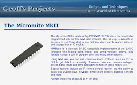
| The main page of the Geoff's site. |
It's about time to create a usefull aplication with.
So, why not to use this circuit with a wifi connection?
Ok, let's go : one wifi board ESP-01 available for a few dollards on the web; a micromite MKII dev board available here; and a tiny LCD display for autonomous use.
 |
| The WIFI module. |
I connected the ESP8266 board with the COM1 basic port of the Micromite, and a 2x16 LCD display as it's explained in the MKII Basic manual.
Some lines of BASIC :
SetPin 15, DOUT
Open "COM1:115200" As #1
Pin(15) = 1
LCD init 18,14,3,25,16,17
LCD 1, 1, "COMMAND AMOUNT :"
Cmd = 0
Do
Line Input #1, dat$
Select Case dat$
Case "led_on"
Pin(15) = 0
Cmd = Cmd + 1
Print #1, "Command nunber ", Str$(Cmd)
Print #1, " ->Led ON"
LCD 2, 1, " "
LCD 2, 1, Str$(Cmd)
Case "led_off"
Pin(15) = 1
Cmd = Cmd + 1
Print #1, "Command number ", Str$(Cmd)
Print #1, " -> Led OFF"
LCD 2, 1, " "
LCD 2, 1, Str$(cmd)
Case Else
Print#1, "Enter led_on or led_off"
End Select
Rem EndIf
It's not a very efficient basic program but I realized this in five minutes.
To test the system, simply connect with a telnet programm at www.electrodiy.com (not the week-end) and switch ON or OFF the led on board, and see the result in your telnet emulator. On my side, I can follow the number of operations directly to the display.
Funny and easy to realize!
I plan to create a more complexe board with a FCC ESP8266 module to take control of my house!


Aucun commentaire:
Enregistrer un commentaire