lundi 5 décembre 2022

Minimalist computing, PLC with an STM32.

Finding a PLC that is relatively simple to use and above all, affordable and also easily expandable is not that easy.

You can use hardware based on Arduino, which costs about a third of what a standard industrial type PLC costs, or use an industrial PLC. The prices range according to the solutions adopted from €300 to €1,200 in Europe, at the end of 2022.

More troublesome, programming software is more or less proprietary and more or less flexible. An Arduino solution will always be more flexible than an OEM solution because you can access CPU resources. What industrial solutions prohibit. but Controllino type boxes are not easy to obtain, especially where I live. It is therefore difficult to offer a finished product in this format.

In fact, and this is my case, if I want to develop specific solutions, neither of the two previously mentioned worlds, Arduino or Industrial, allow me to shape a finished product. I am forced to be dependent on higher layers. From an economic point of view, these upper layers capture most of the added value by producing the least effort because none of these upper layers is in contact with the ground.

To be able to offer specific solutions and at the same time capture the maximum revenue, there are not many solutions. You have to master everything, the hardware, the software and the knowledge that will allow you to do something different but relatively profitable.

Let's go back to the late 80s. PLC standards were not yet established as they are today. So there was some design freedom. Most of the small companies then worked on the VME bus. The advantage was that it was enough to make a printed circuit board and a small front panel to be able to offer a processor or input/output card adapted to the customer's needs.

In fact my basic training allowed me at the time to build complete systems with 68000 processors, based on OS9. It was working very well.

Since that time, generalist manufacturers have increasingly 'closed' hardware and software, so that any personal development is made impossible. Of course, even with proprietary solutions, everything is still possible, but at what cost and with what constraints!

So I decided to create a small processor board olmost VME standard. The bus connector is not VME standard, it is useless. Why? Because an STM32 type processor has absolutely all the internal resources necessary for the development of a PLC. It is just necessary to establish high-speed serial communication links to create a high-performance system at low cost.

Compared to the resources required to create the same type of board based on MC68000, this has absolutely nothing to do in terms of complexity or processing capacity. An STM32 commonly operates at 80MHz, which is 10 times faster than an MC68000@8MHz, especially for PLCs where complex CICS instructions are not used.

So, here is the fruit of my reflections :


This board is only the processor board. It has no inputs/outputs (or almost). It is intended to be supplemented by other cards with various types of interfaces. In the spirit of VME, this allows maximum agility in the configuration of an automatic processing machine.

The result is a very simple design. The software to be used for the development of the application program will be that supplied as standard by STmicro.

In fact, anyone with some knowledge of microcontrollers and C language will be able to program this board. When I have tested it, I will publish the project files thus allowing to start writing code directly.

And in addition, this solution will therefore be open source ;-)

jeudi 10 novembre 2022

Addicted to GoWin fpga's!

It must be recognized that when one has tasted these GoWin circuits and the simplicity of the development software, it becomes very difficult to resist the urge to use them for a whole host of projects.

I had the opportunity, a few months ago, to replace an Intel FPGA-based module with a GoWin module that I made myself, in a project to rebuild the Micro-Professor MPF-1b:

Multitech - MPF-1 / MPF-1B

The result was that : 


I also use a GoWin FPGA in the final version of my MIDI switch. It works very well.
So why not continue with the recreation of an SP12? In fact at first I wanted to recreate a Drumulator. But given the work done on the subject and the little difference in fact with an SP12, I decided to go with an SP12. 

So I gathered the majority of the digital part as well as the sampling in both directions on a small FPGA-based board. 

It should look like this:


I received the circuit boards a few weeks ago and have just mounted the digital parts:


This time the FPGA system is a bit more complex since the circuit is used with some external memory circuits. In fact, the FPGA does not have enough internal memory to accommodate all of the memory associated with the SP12 processor. No room for sample memory either. Also, some of the memory must be non-volatile and this is not possible with the internal memory of the FPGA.

For the moment, I have not powered this board. I will do that in the next few days.
The next objective will consist in starting the program of an SP12 in this board.
Nice challenge!!!

mardi 8 novembre 2022

Korg Kronos main board.

Regarding electronic music devices, I'm more of a 'hold style'. I like beautiful, well-constructed main boards. While consulting on Internet which deal with this subject, I have just discovered that the Kronos range from Korg, works on an Intel motherboard base, and more particularly the D510MO version. 


The first generation of Kronos:

The Intel mother board :


In the idea, why not. The machine works with a customized version of Linux, and some additional boards made by Korg.

But hey, given the price of the machine, we could have expected a professional motherboard, to say the least. But no, this is a low-end motherboard whose long-term reliability is absolutely not the objective.

Personally, I don't really like this way of doing things. We will say that Korg produces good material... but much too expensive for my taste given the way it is developed. You do the same with a low-end PC at 500€, a good sound card and a T1 used for its keyboard and bought for $125 (as me), all for less than $1000!

Note that this probably allows convenient management of the touch panel display. Because for the rest, still very small buttons resembling those of your FM tuner from the 80s, designed to be used 10 times a month like those of the T1. Unacceptable for equipment wanting to be professional!

I may not make friends here, but really, is it serious?!!!

A small audio amplifier based on NE5532.

A small idea, by the way. Why not build a small, compact linear audio amplifier?

In fact, I had the opportunity to test a small amplifier based on an operational amplifier of the TL074 type during the development of the audio part of a Drumulator.

This concept of amplifier exists, obviously. I have only taken examples that can be found on the Internet.

32 circuits equivalent to 64 AOPs are placed in parallel. Push-pull type topology therefore 128 AOPs in service. This should provide enough power for more than adequate rendering. In addition, this circuit does not require any adjustment.

An example of how the circuit can be rendered:

I have some finalizations of track sizes to do and I think I will make this little prototype.


lundi 17 octobre 2022

Attempt to clone an SP12 (3)

I just received the SP12 PCB.


Another circuit to build and test. However, this becomes quite difficult due to the lack of components.

Fortunately, I will be able to test the majority of the functions of the board thanks to a few tips. Some of the components will only be available from April or May next year: terrible situation!

mercredi 12 octobre 2022

MIDI SWITCH(2)

The final production version of the PCB has arrived.

Finally, the printed circuit is very small. I have gathered the MIDI ports in packs of four, which will make it easier to cut out the front panel of the case. I brought back the micro-usb power socket on the front panel.

It is planned to be able to connect a PC equipped with a small software to facilitate the configuration of the switch. I don't have a MIDI ID so I decided not to use the MIDI interface for this.

This possibility, like that of also serving as a USB/MIDI interface, is planned for the next version. 


vendredi 7 octobre 2022

Attempt to clone an SP12 (2)

Construction of the SP12 core continues. I routed the board and sent it to manufacturing.

Preview of routed faces. 

Both sides:


Front face:


And the back :


Finally, a 3D representation:


I just have to wait for the reception of the printed circuits to begin its assembly and the first tests...

mercredi 28 septembre 2022

Attempt to clone an SP12.

Creation of a digital core module for the SP12, with the audio conversion system:


The components are placed. Now I have to route the board!

lundi 19 septembre 2022

MIDI SWITCH

The basic functions of the MIDI switch prototype work well. I'm still developing the system but at the same time, I'm redesigning the printed circuit board. 

The prototype was developed from an Intel OEM FPGA module placed on a motherboard that I created myself. On this motherboard, four connectors connect four small printed circuits each supporting four RJ45 sockets, for a total of sixteen ports.

This way of doing things was perfect for a prototype but not at all suitable for a finished product.
What I particularly appreciate is making it as simple as possible. And since the study from the prototype I experimented with a new type of FPGA more practical to use than Intel circuits, I took the opportunity to redesign the entire switch on a single printed circuit :

The circuit used will allow me to route the MIDI ports but also to perform some processing on the MIDI data. Everything will be programmable using, I hope, a small software running on PC and potentially on MAC.

mercredi 14 septembre 2022

MIDI SWITCH

It's been two months since I posted anything. After the holidays, I strongly put myself in the development of two projects. One of them consists of a 16-ports MIDI rack designed to facilitate the management of the MIDI network within a small music studio.

Although I'm still at the prototype stage, the hardware design is finalized and stable. I am now in the development of the software system. I am progressing step by step in order to create a system offering the essential functions. Subsequently, I will expand the operation by various functions that can be implemented depending on the computing resource that will remain available to me.

This is what the rack looks like:

The challenge is a little bit complicated. A reliable and practical device must be produced at an acceptable cost. And with the current problems of component shortages and rising prices, it really isn't easy!


jeudi 14 juillet 2022

GoWin FPGA & the Wichit Sirichote's µPF--1 clone : subject closed


This time, it's said. I close the topic 'µPF--1 clone'

Why? Because it works.


A few years ago, when I set out to attempt to replicate Wichit Sirichote's work in FPGAs, I developed a minimal system based on the sources of Wichit Sirichote. It had already taken me quite a bit of time to translate all the hardware onto a commercial FPGA board, then develop a personal board to accommodate an FPGA module. I found that it would have taken me too long to re-write a complete system based on poor quality of the source provided. 

And then, I wanted to test the GoWin FPGAs. When I say testing, I mean creating an FPGA board and then programming a complete system. That is to say also test the GoWin development tools.

Free advertising ;-)

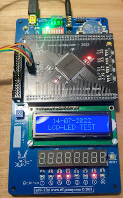
After seeing that the small computer created 'seems' to work fine. I decided to attack what is the center of interest of such a small computer, namely the operation in step by step.

Until then, I had contented myself with re-writing the source of Wichit Sirichote to allow the manipulation of addresses and data as well as the loading of programs by serial link. So I missed the step by step. In terms of real learning of processor operation, step by step is extremely interesting!

It's quite interesting to be able to modify a program value almost on the fly, then to check the result by immediately restarting the program. That's the whole point of such a computer. 

It's a personal opinion, but I find it much more relevant than working on Arduino modules as a discovery of computing.

The system set up for step by step operation is based on an interrupt triggered after a certain number of pulses of the signal M1. Interesting and very functional system. On this point, Wichit Sirichote's source served me well.

So there you go, I have everything set up except the 'REL' key. I couldn't figure out its usefulness, even studying the provided source well. Regardless, it is now possible to write an entire program by directly entering the processor codes, or more simply by loading the program via the serial link and modifying the code directly on the keyboard, starting then stopping the program to check the content of processor registers etc etc...

Small example of a program loaded via the serial link:


The system is therefore validated. The GoWin FPGA used works perfectly. It is a success. I forgot, the serial link works perfectly, here at 115200 Bauds, and not faulty at 1200 Bauds as on Wichit Sirichote's system ;-)
In terms of FPGA resource usage, this is what it looks like:

Barely more than half of the resources in logic gates. I haven't implemented expansion port management, but it only takes a few dozen logical units. Not bad at all!

What's next?

I will now try to set up an HDMI output based on these Gowin FPGAs. Because I would like to develop a real computer with screen and keyboard on which it would be possible to choose the type of processor wanted.

This kind of machine has already been built, notably by Jeri Ellsworth in 2002. It's been just 20 years. It did not meet with much success while the retro-computing craze started to really emerge from the 2010s.


This machine may have come out too soon...

Stefany Allaire is currently recreating a whole range of computers on the same principle. You can visit his website c256foenix.com particularly with regard to its new C256 FOENIX JUNIOR, based on a 6.29MHz WDC W65C02S processor :

Free advertising ;-)

I am really impressed with the quality of his work...

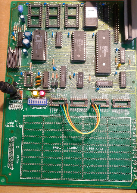
[ 07-16-2022) Small updateAnd now the test with the IOM MPF-1P expansion board.
In fact, I knew that testing the connection of my processor board on the IOM board was going to pose a potential problem. simply because a number of signals used to manage the expansion port are also used for the JTAG programming interface. 

In fact it is not that complicated. All that is needed is to dynamically control the FPGA programming management system. Once done, the operation of the external bus is instantaneous. The connection of the IOM is therefore completely normal. I completed my little test program to turn on the diodes on the IOM board. It works without any problem!


GREAT :-)


The 'funniest' part of the story is that while I added some logical ressources to manage the expansion port, the GoWin software summary report tells me a 50% logical resources usage . It was 52% previously:


I could put two systems like this in the used FPGA considering only the logic resources. However, I wouldn't have enough internal memory for that...

[ 07-18-2022) Small update : For fun, I also connected the small printer, here the PRT-1P model to my processor board :


It seems to work. Why do I say 'seems'? Because I don't own thermal paper. So I can not check if the message is printed correctly. All I can say is that the printer responds correctly to requests made through routines present in the ROM integrated onto the printer board.

I have no idea where to get thermal paper for this machine. Occasionally, I'll try to find some...

mardi 12 juillet 2022

Any other subject : Small automotive remarks.

As an indication, I have never worked in mechanics. So I have no practice on the subject.

Times being what they are, in France, we are now confronted with exorbitant vehicle maintenance costs and a lack of professional skills in conventional mechanics.

And yes, you have to go electric. Hmm, for a whole bunch of reasons, I don't think going electric is the solution to the planet's problems, any more than to energy independence.

I even think that the switch to electric is a big mistake. I am much more in favor of a reasoned use of energy, and of adapting to a low-consumption lifestyle.

I own a Renault vehicle, but I should say Matra, since 1998. It now has 250,000 km. It's a 3L V6 engine. I don't use it much, as little as possible in town. I really appreciate this vehicle for its comfort and the simplicity of its operation.


I'm not going to tell the story of the Matra car brand here. To sum up, this is a company which has produced vehicles that are always quite special, which has greatly distinguished itself on the racing circuits, and which definitively closed the doors of its Romorantin-Lanthenay site on February 26, 2003.

Entrance to the site today :


Part of the interior of the production site:

This site is now a large green space, surrounded by new housing construction, as well as a large rest center for old people. Sad end... for such a great company

Well, actually, my car is almost a collector's car. 

As it works very well, I want to keep it in working order. So, for that, I realized my first mistake!

Indeed, we must regularly pass our vehicles to the technical control. Last time it said there were engine leaks. This does not surprise me since there is no one left to carry out the maintenance work. So, as I don't use it much, I haven't done any maintenance for a long time.

In order to go back to the technical control, after having changed a part on the front axle anyway, I decided to clean the engine with a water jet.

In principle this is not a problem. Before performing this operation I had researched information on this subject without finding anything embarrassing. So I cleaned the engine. Everything worked very well. A few minutes later, the engine still started to misfire.

Of course, I suspected what had happened. 

And this is where the real problems begin. I had to remove the coil ramp to access the spark plug wells but I didn't have the tools, of course... I had to wait a while to finally find a TORX T30 wrench.

I expected to find carnage when I removed those coils. I was not disappointed:


Inevitably, in this state, it was not likely to work properly. I even wonder how the engine managed to start in these conditions. Anyway, pistons were 'missing' and you could hear it. There was only one thing left for me to do. Clean all this dirt as best as possible and also remove as much visible rust as possible on the central well:


It's already better! 

After reassembly, the engine works normally again.

However, I still have to change the spark plugs because with the rust, they might weld on the cylinder head. I also need to change the coil ramp. It has plastic parts that are beginning to deteriorate. And anyway, the contact springs have rusted as well. I even think it was one of them that caused this beautiful rust in one of the spark plug wells.

Concussion: do not pass an engine to pressurized water when it has spark plug wells. The coil ramp is not waterproof and lets water through to the spark plugs!

I just have to get the new parts, as well as a spark plug wrench, diameter 16mm!

GoWin FPGA & the Wichit Sirichote's µPF--1 clone.

I've been testing the Wichit Sirichote's µPF--1 compatible development board for a few years now.


Here are all the studies carried out around this system:
  • 2017 - Achievement of the kit with the basic system available in 2017.
  • 2018 - Attempted modification with the system update: large number of malfunctions including the serial link.
  • 2019 - Study of the system on a commercial FPGA board. Modification of the code for a functional serial link.
  • 2020 - Realization of a personal board based on Intel FPGA and installation of the system with the operation of the serial link corrected.
  • 2022 - Porting VHDL code to GoWin FPGA. The goal is to test the operation of these new FPGAs.

Until now, I had only taken care of the rewriting of the code of Wichit Sirichote concerning the operation of the serial link. I had not particularly tested the other functions of the monitor other than those relating to the ADDR and DATA keys, allowing the contents of a memory address to be viewed, and to be modified if necessary.

On the occasion of the transition to the GoWin FPGA, I decided to test all the keys allowing autonomous operation of the system. And there, big surprise. The code is buggy everywhere!!!

Until now I thought the problems were mostly around the serial port. actually no. I almost have to re-write the whole system.

In fact: Wichit Sirichote provides the Hexa file of the first version of the system. The source is only provided for the latest version, the one where the serial port does not work.

After having worked hard on this source code, I think that this source is in fact a very first development version and does not correspond to the first version provided, nor to the very last one.

If the source provided allows you to get a good idea of ​​how the system works, it is so badly written and so dysfunctional that everything has to be rewritten.


Even getting to this error message (generated on purpose for the photo), it wasn't easy. I chose an end address lower than the start address for the memory block copy function. What generates this error!

In a nutshell: Wichit Sirichote's idea was very good. But do not try to draw inspiration from the sources provided to make your own monitor. It's a guaranteed waste of time. It is better to develop your own monitor from scratch!

Apart from the REL key, the function of which I am unable to determine what it does, even from the source, all the functions except the DUMP and the LOAD are functional. In particular the step-by-step function which involves the use of the NMI interrupt of the processor.

It only remains for me to implement the serial link for the LOAD/DUMP function in the FPGA and to copy all the modifications that I have already made to the source concerning the management of this serial port.

I wanted to see if I could make the same type of system with the GoWin FPGAs as with those from Intel that I usually use. I must say the result is absolutely perfect.

I had to write a small utility to provide the RAM initialization file in GoWin format. Nothing too complicated to do. Thereafter, the development procedure is carried out in the same way as with the Quartus development chain.

I will quietly finalize the development of this system and will test everything concerning the HDMI outputs because GoWin seemed to provide this type of output on its FPGAs. In fact, now that I'm in a position to develop a relatively complex but basic system, I would really try to build a more standard small computer, i.e. with a normal keyboard and video output...

I had to develop a Drumulator clone, but given the power of these FPGAs, I'm going directly to develop an SP12 or SP1200 clone. As I tested all the sub-elements of the Drumulator, it shouldn't be too complicated to get started with the SP12/SP1200 since it's exactly the same operating principle, but in 12 bits...


mardi 5 juillet 2022

GoWin FPGA & µPF--1

To finalize my uPF--1 compatible board, I decided to implement the Wichit Sirichote's project


I have already done this work a few years ago, but based on an Intel FPGA. Since then, I have improved in the VHDL language. 

So I take advantage of this to code the whole machine again in this GoWin FPGA, also taking advantage of the improvements made by the new versions of certain components and the SDCC compiler, as well as the modifications that I have made myself.

This little development machine is very interesting. It allows you to become familiar with the operating principles of microprocessors. 

Modern processors like ARM for example, still work the same way. Understanding how a Z80 works is a very good learning exercise. Much better I think than Arduinos, which, if they have a whole bunch of 'fun' advantages, mask a large part of the real functioning of the processors.

And now with the startup messages:


At the time, I called my work uPF--2. I will continue to name this little machine that way.

This is not a priority project. I will advance it as I can, over time...


vendredi 1 juillet 2022

Chinese components and GoWin FPGAs. Is it worth?

It's been a few years since I mentioned the rise of China in the supply of original components. GoWin is one of those companies that for several years has developed a series of FPGAs.


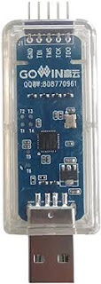
So I thought it was time to try this type of components. For this I managed to get the programming tool GWU2X :


The development software tool is available directly on the GoWin site. I also had to find a development board equipped with an original GoWin FPGA. I couldn't really find what suited me on the market, so I decided to develop my own board, in Qmtech format, since I had developed a few projects with this board format: 


Very recently, I managed to implement the 'Hello World' (the blinking led) on this board. The next step was very ambitious, namely trying to implement a complete Z80 system within this FPGA. 

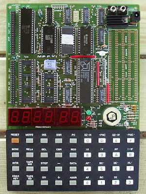
So, I chose to try installing the Microprofessor version 1B system on the electronic board dedicated to this small vintage computer:

The uPF--1 original board
It took me a few hours to familiarize myself with the GoWin development environment, as well as to make the necessary small modifications to my VHDL code to make this FPGA compatible with the uPF--1 system. 

So, after a few hours of work, the result is there:


I did not attempt to implement all the hardware resources of the uPF--1, that was not the goal. I just wanted to see if I could get the same services with this FPGA as with the ones I usually use like Altera (Intel now) circuits. The goal is reached. I now think I can continue to develop using these GoWin circuits.

Conclusion: I appreciate these circuits which seem to me easier to use than the Xilinx or Altera circuits. The entire development chain is easy to understand. The necessary resources are available on the web. There are few ways of doing of the software development that could be improved a bit. But this is more of a personal matter...

In short: practical component to use. Easy to use development chain: cool!